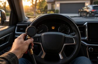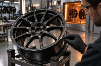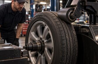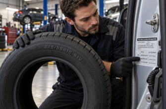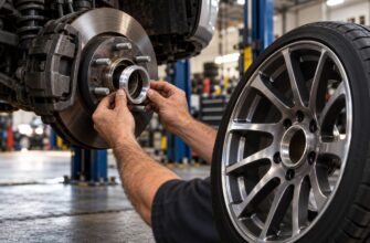
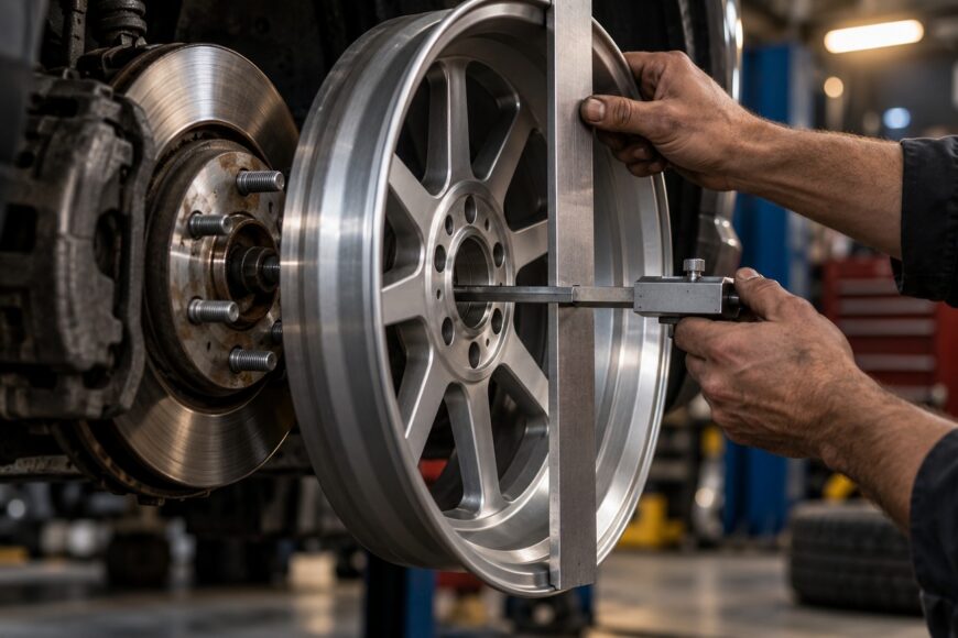
A wheel can match the vehicle’s bolt pattern and still rub the strut, spring, brake caliper, or fender. The mounting holes confirm only that the wheel can attach to the hub. They do not establish enough space around the tire, suspension, or brakes once the steering turns and the suspension moves.
Offset and backspacing describe related wheel positions through different measurements. Offset, or ET, uses millimeters from the mounting face to the wheel’s geometric centerline. Backspacing uses inches from the mounting face to the inner bead-seat edge. Width, tire shape, suspension travel, vehicle load, and brake design must be considered with either value.
A catalog specification is therefore a starting point, not a physical clearance test. Calculate the change from the factory wheel, then verify the actual wheel and tire at full steering lock and relevant suspension compression. That is how you find the interference that a bolt-pattern search or a parked-car inspection can miss.
- What Wheel Offset and Backspacing Actually Measure
- How to Convert Backspacing to Offset
- Why Wheel Width Changes the Fitment Even at the Same ET
- The Fitment Checks Numbers Cannot Replace
- How to Check for Rubbing Before You Drive
- Common Offset and Backspacing Mistakes to Avoid
- Frequently asked questions
- What does 4.5-inch backspacing mean?
- What is 5.5-inch backspacing in offset?
- What is the offset for 4.5-inch backspacing?
- How does a wheel spacer change effective offset?
What Wheel Offset and Backspacing Actually Measure
Wheel offset is the distance from the wheel mounting face to its geometric centerline, measured in millimeters. The mounting face is the surface that sits against the hub. The centerline divides the wheel’s nominal width into two equal halves, so ET describes how far that centerline is positioned relative to the hub.
Positive offset moves the wheel inward toward the vehicle. The mounting face sits closer to the outside face of the wheel, leaving more of the wheel’s width on the inboard side. Negative offset moves the wheel outward away from the vehicle, increasing the wheel’s outward position and usually making the fitment look more “deep dish.” Zero offset places the mounting face at the geometric centerline.
Backspacing is the distance from the mounting face to the wheel’s inner bead-seat edge, measured in inches. It describes the inboard depth of the wheel rather than its position in millimeters. A larger positive ET usually means greater backspacing, although wheel width and the measurement method must also be considered.
These are connected measurements, not interchangeable labels. Backspacing in inches cannot be compared directly with ET in millimeters, and neither measurement alone proves that a wheel fits a particular vehicle. The same backspacing can produce different offset values on wheels of different widths, while the same ET can place different wheel widths at different inner and outer edges.
How to Convert Backspacing to Offset
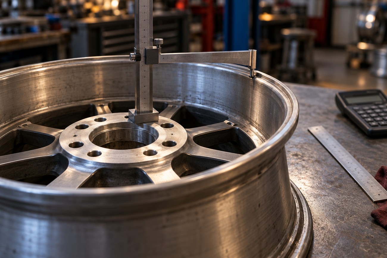
For a wheel whose width is stated between the bead seats, the usual forward conversion is:
Backspacing ≈ (W + 1) / 2 + ET / 25.4
Here, W is the nominal wheel width in inches, and ET is in millimeters. The added 1 inch accounts for the wheel flanges when the quoted width is the bead-seat width rather than the full outside width. The value 25.4 converts millimeters to inches.
To calculate offset from a known backspacing value, use the reverse relationship:
ET ≈ [backspacing − (W + 1) / 2] × 25.4
A backspacing number without the wheel width cannot produce one definitive ET. For example, 4.5 inches of backspacing represents the same inboard depth, but its offset changes according to the total wheel width. The calculation must also use the width measured between the bead seats unless the supplier clearly states another reference.
Small discrepancies are common when a seller measures from a different edge, rounds the result, or uses a specification based on the wheel’s control geometry. Nominal width is usually the bead-seat width, not the full outside width across the flanges. Treat a calculated value as geometry for comparison, then confirm the wheel’s actual marking and clearances before ordering.
Why Wheel Width Changes the Fitment Even at the Same ET
Wheel width and offset work together to determine clearance to struts, springs, control arms, brake components, and the fender. The claim that identical ET creates identical fitment is therefore incomplete. ET locates the wheel’s centerline relative to the hub, while width determines how far the inner and outer edges extend from that centerline.
At the same ET, increasing wheel width moves the added width approximately half inward and half outward. A wider wheel can therefore lose clearance to a suspension component while also moving its outer lip closer to the fender. Reducing one problem with a different ET can create another, because moving the wheel outward changes the outer position and the loads carried by the hub and related components.
Inner clearance and outer poke should be measured separately. Inner clearance covers the gap to the strut, spring, control arm, brake assembly, and other chassis parts. Outer clearance covers the tire and wheel relative to the fender lip, splash shield, and bodywork. A wheel can clear the strut yet rub the fender under compression, or clear the fender while touching the suspension at full steering lock.
The tire can become the first point of contact even when the wheel appears to have adequate space. Tires with the same nominal size can have different actual widths and shoulder shapes between manufacturers. The sidewall and shoulder can extend beyond the wheel, so the final check must use the actual tire rather than relying on the label or wheel dimensions alone.
The Fitment Checks Numbers Cannot Replace
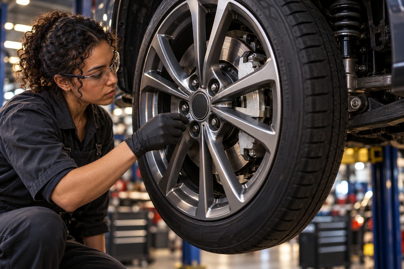
Correct bolt pattern and a plausible ET do not guarantee complete compatibility. The brake caliper may have a different shape or sit farther out than the original component. Spoke design also matters: a wheel can have enough barrel diameter yet leave insufficient clearance between the spokes and the caliper face.
Hub-bore compatibility is a separate check. A wheel with a larger center bore may need an appropriate centering solution, while a smaller bore may not seat on the hub at all. The wheel’s load rating must also suit the vehicle and its intended use. These details remain relevant even when the wheel’s basic dimensions appear correct.
Keeping the replacement offset as close as practical to the factory value is a sound professional baseline unless the vehicle manufacturer permits another setup. This does not make the factory ET an absolute rule for every wheel, tire, or brake conversion. It limits unnecessary changes in scrub geometry, track width, and component loading while leaving the other fitment checks in place.
Moving the wheel outward increases track width and can increase loads on the hub, steering, and suspension components. The exact effect depends on the vehicle, tire, mass, and road loads. A wheel that does not visibly rub can still change steering feel, increase steering effort, or contribute to accelerated wear if the new position is outside the intended design range.
Spoke clearance deserves a separate physical inspection because it cannot be inferred from backspacing alone. Two wheels with the same width, ET, and bolt pattern can have different spoke curvature and brake clearance. Catalog language such as “plug-and-play” describes a seller’s fitment category, not a substitute for checking the caliper envelope, hub fit, load rating, and dynamic clearance.
How to Check for Rubbing Before You Drive
Begin with the actual wheel and tire mounted on the vehicle. Inspect the inner sidewall and wheel against the strut, spring, control arm, brake components, shields, and other fixed parts. Then inspect the outer shoulder, sidewall, and wheel lip against the fender and liner. Measure the narrowest gap rather than judging the wheel’s overall appearance.
Turn the steering through full lock in both directions and check the points that move relative to one another. Straight-ahead clearance can look generous while the tire approaches a liner, control arm, or splash shield at maximum steering angle. On driven wheels, the tire’s shoulder and sidewall often reveal contact before the wheel itself does.
Require clearance checks at full lock and maximum relevant compression with the actual tire mounted; a wheel-only measurement can miss sidewall and shoulder contact.
Check the vehicle at the maximum relevant suspension compression, including the loaded condition that the vehicle may regularly experience. A wheel that clears while stationary and unloaded can rub when passengers or cargo compress the suspension. Mud, tire chains, protective shields, and manufacturing tolerances can consume an apparent gap as well.
Do not treat zero visible contact on a stationary vehicle as a safe margin. The tire flexes, the suspension changes position, and the body can move relative to the wheel. Terms such as “aggressive fitment” may describe a compromise involving rubbing, fender protrusion, higher component loads, or the need for additional adjustment.
Use catalog fitment information to identify likely candidates, then verify the physical result. The final assessment should include both inner and outer clearance, full steering lock, maximum relevant compression, the actual tire dimensions, and the vehicle’s intended load. A static check that covers only one of those conditions is incomplete.
Common Offset and Backspacing Mistakes to Avoid
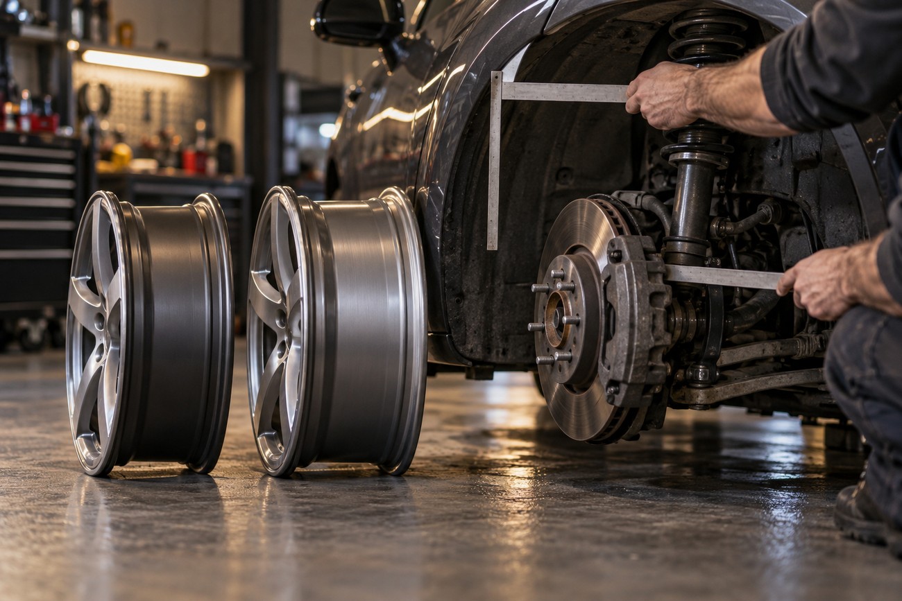
The most common calculation error is comparing ET values while ignoring wheel width. A wider wheel with the same ET changes both the inner and outer edges, so the apparent similarity in the catalog can conceal a smaller strut gap and greater fender exposure. Compare each edge separately against the current wheel before assuming the new position is equivalent.
Backspacing creates a second set of errors when the seller does not state how it was measured. The result may be taken from a different reference edge, rounded, or confused with the full outside width. Ask for the nominal width between the bead seats and the exact backspacing method. Without those details, a conversion can look precise while describing a different geometry.
Measuring from the geometric edge of the wheel instead of the bead-seat reference also produces a misleading result. The standard formula includes the flange allowance because nominal width is normally the distance between bead seats. A measurement that mixes full outside width with bead-seat width should not be inserted into the formula without adjustment.
A spacer changes the effective offset by approximately its thickness in millimeters toward a more negative value. A spacer of a given thickness moves the wheel outward by roughly that same thickness, increasing track width and changing inner and outer clearance. The absence of rubbing does not eliminate the possible change in hub, steering, or suspension loading.
Before using a spacer, verify thread engagement, hub centering, permitted load, and the fit of the wheel to the spacer. The spacer must also be suitable for the hub and wheel interface, rather than serving only as a visual adjustment. After installation, repeat the full-lock, maximum-compression inspection because the spacer changes the geometry at every clearance point.
Frequently asked questions
These questions address common backspacing conversions and the checks that remain necessary after calculating effective offset. The formulas require the wheel’s nominal width, and physical clearance still must be verified on the vehicle.
What does 4.5-inch backspacing mean?
4.5-inch backspacing means the distance from the wheel’s mounting face to its inner bead-seat edge is 4.5 inches. It describes the wheel’s inboard depth, measured from the surface that contacts the hub to the inside bead-seat reference.
That value is not a complete fitment specification and does not identify one offset by itself. Wheel width is also required for the conversion, and the result still does not confirm caliper, hub-bore, tire, or fender clearance.
What is 5.5-inch backspacing in offset?
There is no single offset for 5.5-inch backspacing without the wheel width. Supply the wheel’s nominal width measured between the bead seats, then calculate ET with ET ≈ [backspacing − (W + 1) / 2] × 25.4.
The same 5.5-inch backspacing can correspond to different ET values on different wheel widths because the wheel centerline changes. Confirm that the supplier’s backspacing uses the same bead-seat reference before treating the result as comparable.
What is the offset for 4.5-inch backspacing?
A valid conversion requires the wheel width, so 4.5 inches cannot be assigned one universal ET. Use ET ≈ [4.5 − (W + 1) / 2] × 25.4, with W in inches and measured between the bead seats.
Different wheel widths produce different offsets from the same 4.5-inch backspacing. A catalog shortcut that omits width can therefore give a misleading answer, even before differences in measurement method and actual vehicle clearance are considered.
How does a wheel spacer change effective offset?
A spacer reduces effective offset by approximately its thickness in millimeters, making the effective ET more negative. It moves the wheel outward by roughly the spacer thickness, which changes inner clearance, outer poke, track width, and component loading.
Installation also requires checks for thread engagement, hub centering, wheel and spacer fit, and permitted load. Recheck brake, suspension, fender, and tire clearance at full steering lock and maximum relevant compression after the spacer is fitted.