
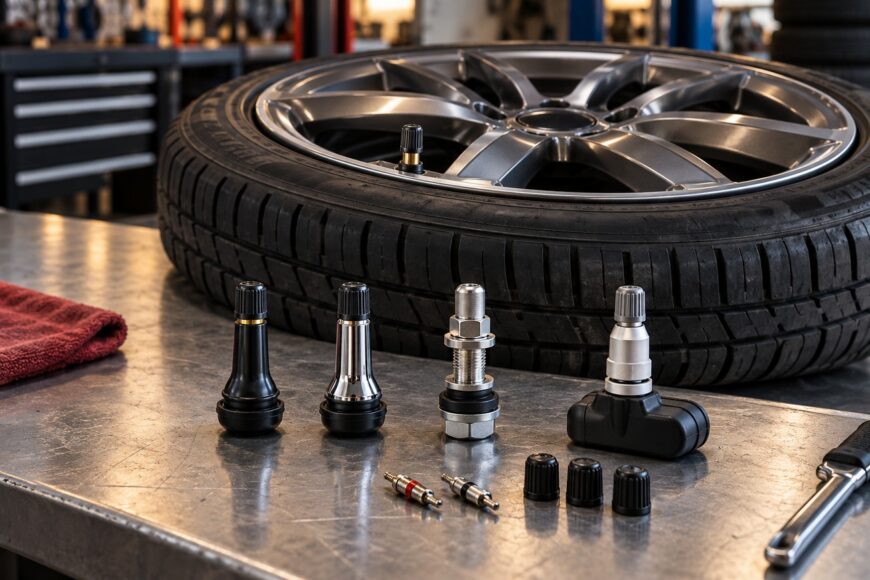
A replacement stem can appear to fit during assembly, yet the valve still leaks, binds, or fails to connect to its actuator. Matching the visible length and diameter is rarely enough. The stem’s motion, its connections to the closure element and operator, and the surrounding seals all affect whether the repair works.
A valve stem transmits motion from a handwheel or actuator to the closure or control element. That job puts it under mechanical load while its surface may also face corrosion, wear, and repeated contact with seals or guides. Identifying the stem arrangement first makes it easier to find the right part and diagnose what actually failed.
- How valve stems move and why the design matters
- Valve stem types and matching checks by valve design
- Identify the exact replacement before ordering
- Is the stem faulty, or is the leak in the packing?
- Replace a valve stem without compromising pressure safety
- Why new stems fail: seals, alignment, and material
- Frequently asked questions
- What is the difference between TR13 and TR15 valve stems?
- What should I do if a valve stem breaks while the line is pressurized?
- How do I know what kind of valve stem I need?
- What types of valve stems are there?
How valve stems move and why the design matters
Stem descriptions often refer to motion rather than a complete part specification. Rising, non-rising, sliding, and quarter-turn rotary stems move differently, so a replacement must match the valve’s operating mechanism. Two stems in the same broad category may still have different threads, drive ends, or connections to the closure element.
A rising stem moves outward as the valve operates, making its travel visible. That helps an operator assess position, although the installation needs clearance for the stem’s full movement. A non-rising stem turns without the same visible outward travel; position may instead need to be checked through an indicator or the valve’s operating arrangement.
OS& Y, or outside screw and yoke, describes an arrangement rather than a separate category of valve. It places the stem thread outside the pressure boundary, away from the process medium. Its exposed rising stem supports visual position checks, while the yoke and stem travel need space and protection suited to the installation.
Sliding stems move linearly without relying on a rotating stem thread for their operating travel. Quarter-turn rotary stems typically rotate 90° to move a disc, ball, or other closure element. Neither motion is inherently superior: the valve design, available space, required indication, and service conditions determine what belongs in the assembly.
Valve stem types and matching checks by valve design
Use the motion category to narrow the search, then compare the actual mating features. Typical applications are guides, not promises that parts from different valves will interchange.
| Stem motion or arrangement | Typical valve application | Motion and position indication | Mating features to check |
|---|---|---|---|
| Rising threaded | Gate or globe valve, depending on design | Stem travels outward; travel provides a visible position cue | Thread form, nut, closure connection, stroke, and clearance |
| Non-rising threaded | Gate valve in an arrangement with limited external clearance | Stem rotates without equivalent outward travel; position needs another indication | Internal thread engagement, thrust features, operating end, and closure connection |
| Sliding | Actuated control or other linear-motion valve | Stem moves linearly; indication depends on the actuator and valve assembly | Stem-to-closure coupling, guide fit, seal contact area, and travel |
| Quarter-turn rotary | Butterfly or ball valve | Stem typically rotates 90°; an external indicator may show position | Square, D-shaped, or other drive profile; disc or ball connection and retention |
A through-stem and a two-piece stem are design-dependent rotary arrangements. Their connections to the closure element and their retention details can differ even when the valve size and actuator mounting appear alike. Order the arrangement shown in the valve’s drawing rather than treating either as a universal substitute.
Position indication also has limits. Visible travel shows what the stem is doing, while a damaged stem-to-closure connection can allow movement without the expected closure movement. If indicated position and valve performance disagree, inspect the complete drive path under the manufacturer’s maintenance procedure.
Identify the exact replacement before ordering
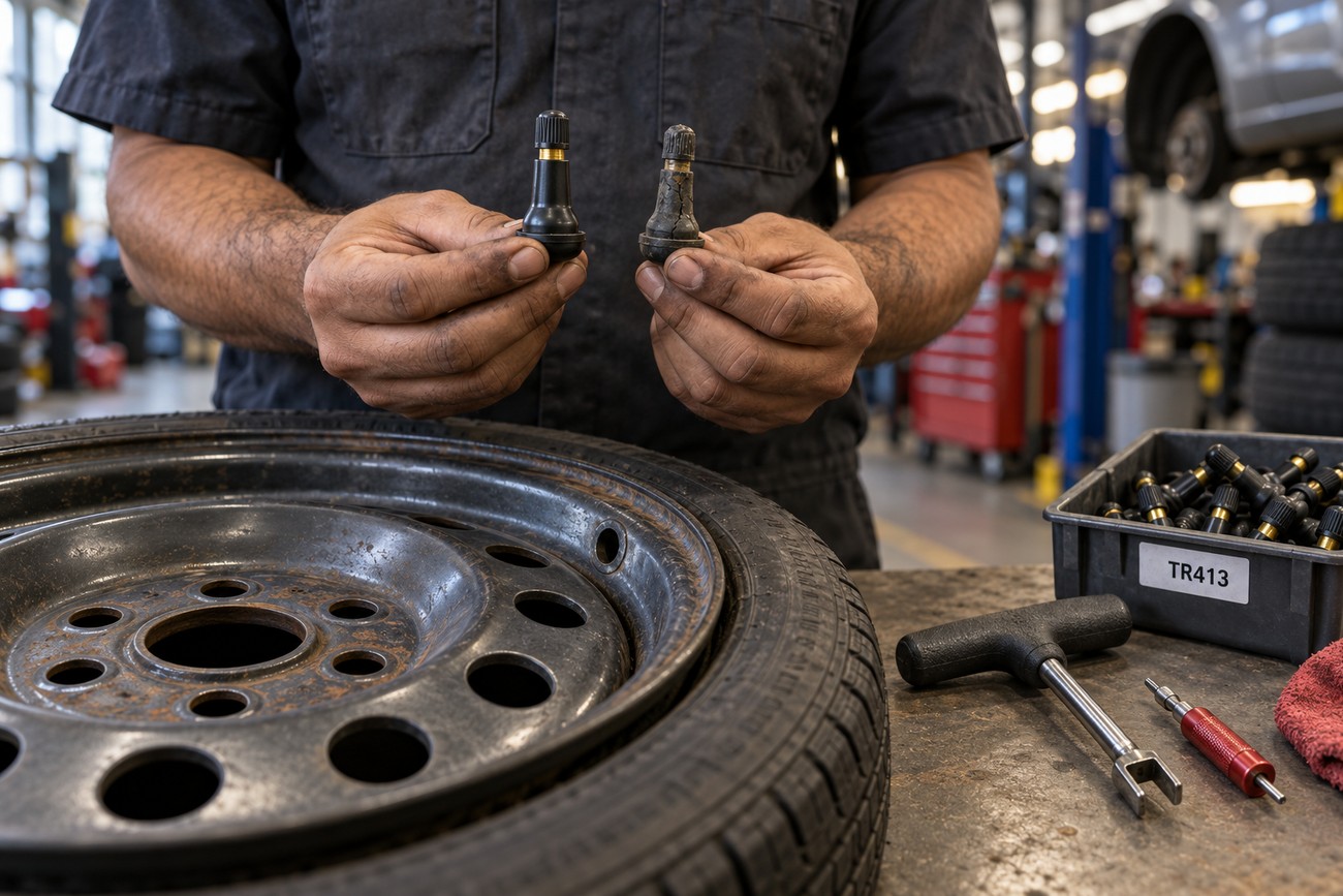
Start with the valve identification plate and any markings on the actuator or handwheel assembly. Record the valve model, size, pressure rating, and relevant service details, then obtain the manufacturer’s drawing or parts list for that configuration. A photograph can help identify a feature, but it cannot confirm an internal thread or hidden retaining part.
Compare the specified stem motion, overall and working dimensions, travel or rotation, threads, and drive-end profile. Check what mates with each end: the stem nut, coupling, disc, ball, plug, or other closure element. Include guides, thrust parts, and stem seals in the comparison, because a new stem fitted to worn mating parts may still bind or leak.
For a quarter-turn assembly, check the actuator mounting and the drive connection separately. ISO 5211 specifies quarter-turn actuator mounting interfaces; it does not establish universal stem interchangeability. A matching mounting pattern can coexist with a different square, D-shaped, or other drive profile, as well as a different stem-to-disc connection.
Common industrial stem material families include stainless, carbon, and alloy steels, but suitability depends on the medium, temperature, wear conditions, and valve design. Confirm the specified material and any surface treatment rather than substituting an apparently stronger grade. Verify actuator torque compatibility against the valve and stem design as well as the physical connection; a drive that fits can still overload the assembly.
Is the stem faulty, or is the leak in the packing?
Leakage visible around a stem does not, by itself, identify a damaged stem. Packing or another stem-sealing component may be the leak path. Note where fluid appears and whether leakage changes during operation, then use the valve’s maintenance instructions to determine which parts require inspection after safe isolation.
Hard operation points to a different set of possibilities. Corrosion or wear on the stem can increase friction, while worn guides or misalignment can make an otherwise sound stem bind. Lost motion may indicate wear at the stem-to-closure connection rather than damage along the stem’s sealing surface.
Where the stem and disc, ball, or other closure element form a mating drive connection, damage to either side can accelerate wear on the other. Inspect both contact surfaces for rounding, galling, or movement beyond the valve’s specified fit. Replacing one visibly worn component while leaving its damaged mate in place can reproduce the same complaint.
Assess the seals before deciding the scope of the repair. A sound replacement stem will not correct packing that has lost its seal, and forcing a difficult valve can add damage. The inspection findings, parts drawing, and manufacturer’s limits should determine whether the work involves a stem, sealing parts, guides, or a larger assembly.
Replace a valve stem without compromising pressure safety
Stem replacement is a valve-specific maintenance task, not a universal teardown. Identify the exact assembly and obtain its procedure and replacement parts before opening it. Plan for the line contents and any trapped pressure in connected spaces; do not assume that closing the valve itself makes stem disassembly safe.
Isolate the line, lock out the equipment and actuator as required by site procedures, depressurize, and drain or otherwise make the assembly safe for its service. Verify safe conditions before loosening packing hardware, retainers, or the stem. If isolation cannot be confirmed, stop and have qualified personnel address it.
Once safe, record the operator position, stem orientation, couplings, and the order of removed components. Follow the manufacturer’s sequence so thrust parts and retainers remain identifiable. Inspect the stem’s mating surfaces, guides, closure connection, and sealing contact area before installing a new part.
Assess packing and every other disturbed seal, renewing them where the manufacturer’s instructions require it. On applicable butterfly valves, API 609 addresses anti-blowout stem retention; the specified retention components must remain effective after reassembly. Never omit a retainer simply because the stem appears secure with the actuator attached.
Reassemble using the specified parts, orientation, adjustments, and tightening procedure. Check that the valve completes its intended travel without binding and that the actuator and position indication agree with closure movement. Perform the prescribed leakage and operational checks before returning the line to service.
Why new stems fail: seals, alignment, and material
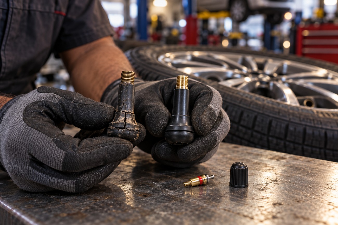
A successful installation can fail early if the original leak path remains. Reused or damaged packing may continue to leak around a new stem, and a worn guide can press that stem unevenly against the seal. Look for the cause of uneven contact before fitting another replacement.
Alignment matters across the full drive path. A misaligned actuator coupling or worn connection to the closure element can make the valve stiff, create lost motion, or mark the new stem. Forcing a handwheel or increasing actuator effort to reach the closed position may conceal the fault briefly while adding load to the parts.
Material choice needs the same discipline as dimensional matching. Stainless, carbon, and alloy steels serve different valve designs and conditions; none is suitable for every medium or temperature. A specified 17-4PH stem or a hard surface treatment may address a particular duty, but neither is an automatic upgrade for another valve.
Before closing a repeat-failure work order, compare the failed part with the drawing and record the condition of the seals, guides, and mating drive surfaces. Confirm actuator torque compatibility against the valve and stem design. Those checks separate a defective replacement from an assembly that is damaging each stem installed in it.
Frequently asked questions
These short answers address identification and immediate safety decisions. For disassembly, the valve’s instructions and site procedures remain the controlling references.
What is the difference between TR13 and TR15 valve stems?
TR13 and TR15 are tire valve stem designations, not industrial valve stem motion types. If you are replacing one, use the wheel-hole and tire-valve specifications to identify the correct fit; an industrial valve parts list will not establish it.
What should I do if a valve stem breaks while the line is pressurized?
Do not touch or loosen the stem, packing, actuator, or retaining parts. Keep people clear of the affected area and arrange isolation through site procedures and qualified personnel. Treat the assembly as pressurized until safe conditions have been verified, even if visible leakage is limited.
How do I know what kind of valve stem I need?
Use the valve’s model and configuration to find its manufacturer’s parts drawing, then match the specified part to the stem and its mating components. If the identification plate is missing, document the valve and operator markings and seek confirmation before ordering; similar external dimensions alone do not establish interchangeability.
What types of valve stems are there?
Industrial valve stems are commonly described as rising, non-rising, sliding, or quarter-turn rotary according to how they move. These are useful identification categories, not complete replacement specifications: threads, stroke, drive profile, seals, and closure connections still depend on the particular valve.