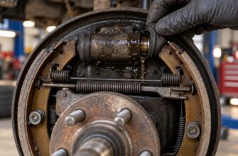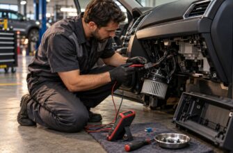

An ABS warning may point to one wheel without identifying the part that failed. A wheel-specific fault code can lead you to the sensor, yet a damaged wire, corroded connector, or faulty hub can produce a similar warning. Buying a sensor before checking the signal may leave you with the same light and an unnecessary part.
Start with the fault code, inspect the circuit, and compare wheel-speed readings if your scan tool can display them. Once the evidence supports replacing the sensor, check how it mounts on your vehicle before taking the wheel off. Some sensors come out cleanly; corrosion can turn others into an extraction job.
- Confirm the sensor is the fault before buying one
- Prepare the car and check the replacement part
- Remove the old sensor without damaging the hub
- Install the new sensor and route its lead correctly
- Clear the fault and verify the repair on a road test
- If the ABS warning returns, look beyond the new sensor
- Frequently asked questions
- How much does it cost to replace a bad wheel speed sensor?
Confirm the sensor is the fault before buying one
A wheel speed sensor reports how quickly its wheel turns. ABS, traction control, and electronic stability control (ESC) use that signal; some vehicles also use it for the speedometer or driver-assistance features. A failed signal can therefore affect more than one warning lamp or function.
Read the ABS fault with a scan tool that can access the ABS system. A wheel-specific code identifies a circuit or wheel to investigate; it does not by itself prove the sensor is defective. Start at that wheel and follow the lead toward its connector, looking for cuts, rubbing, trapped sections, loose clips, moisture, and corroded contacts.
If the tool shows live data, compare the wheel-speed readings during slow, safe movement as the vehicle procedure permits. A missing, erratic, or periodically dropping reading helps narrow the search. Where accessible, inspect the hub bearing and encoder or magnetic ring for damage; a sensor cannot produce a reliable reading from a damaged target.
Identify the sensor type before electrical testing. Passive and active sensors require different checks, so a generic resistance reading or AC-voltage threshold can mislead you. Even published resistance, output, and air-gap figures apply only to the systems and procedures that specify them; use the service information for your vehicle.
Prepare the car and check the replacement part
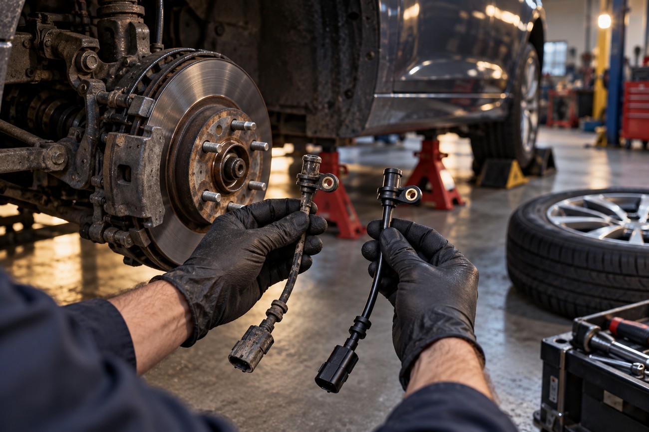
Consult vehicle-specific service information for access, attachment, tightening requirements, and any specified clearance. Confirm whether the sensor is a separate service part or is integrated into the hub. An integrated sensor or encoder can change the job from a small-part replacement to hub assembly work.
Work on a level surface, chock the wheels that remain on the ground, and support the vehicle at its specified lifting points before removing a wheel or rotating a raised hub. Never rely on a jack alone. If access requires work beneath the vehicle, make sure it is securely supported before reaching in.
Compare the replacement with the original part and the vehicle specification. A matching plug does not establish that the sensor type, connector arrangement, polarity where applicable, or position relative to the encoder is correct. Resolve a mismatch before installation rather than using the road test to discover it.
Remove the old sensor without damaging the hub
Locate the sensor lead and trace its route before disconnecting it. Release the connector and cable clips without pulling on the wire, then remove the sensor fastener. Keeping track of the original route will make it easier to protect the new lead during installation.
Ease the sensor body from its mounting bore using the removal method specified for the vehicle. Corrosion can seize the body or fastener, and pulling harder on the cable can break the sensor while leaving part of it in the hub.
A seized sensor that starts to crack or distort is an extraction job. Stop before a broken body or damaged mounting bore turns a sensor replacement into hub work.
Once the sensor is out, inspect the bore and mounting surface for rust, debris, and damage. Clean them by the approved method without enlarging or reshaping the seat. Rust left beneath the new sensor can change its position relative to the encoder and degrade the signal.
If removal has damaged the bore, fastener threads, or surrounding hub, assess that damage before installing the new part. Forcing a sensor into an altered seat can conceal the problem until the ABS warning returns.
Install the new sensor and route its lead correctly
Seat the specified sensor against a clean mounting surface and secure it using the vehicle’s fastener instructions. Sensor-to-encoder clearance is system-specific; do not set a universal air gap. Avoid thick paint or sealant on the seat, because added material can shift the sensor from its designed position.
Check that the connector contacts are clean and sound, then connect them fully. Trace the original cable route and secure every clip. Leave the lead clear of the tire, moving suspension and brake parts, and hot components throughout their normal range of movement.
Before refitting the wheel, look over the complete lead rather than only the new sensor. A cable pinched behind a bracket or left to rub can recreate the fault despite a correctly installed part. Reassemble the wheel and tighten its fasteners to the vehicle specification.
Clear the fault and verify the repair on a road test
With the vehicle safely reassembled, check the lead routing once more. Clear stored ABS faults with a capable scan tool where the vehicle procedure requires it, then follow any specified self-test or drive procedure. The ABS light may remain on until faults are cleared, the vehicle moves, or that procedure is completed.
Make a cautious verification drive in a suitable place. If live data is available, compare the wheel-speed readings, including at low speed and through gentle turns where safe. The repaired wheel should report consistently alongside the others, without missing or periodic dropouts.
Rescan the ABS system afterward. A stored fault that does not return after the required checks differs from a fault that reappears immediately or during movement. If the warning returns, use the new code and live data to guide further diagnosis rather than replacing another part on suspicion.
If the ABS warning returns, look beyond the new sensor
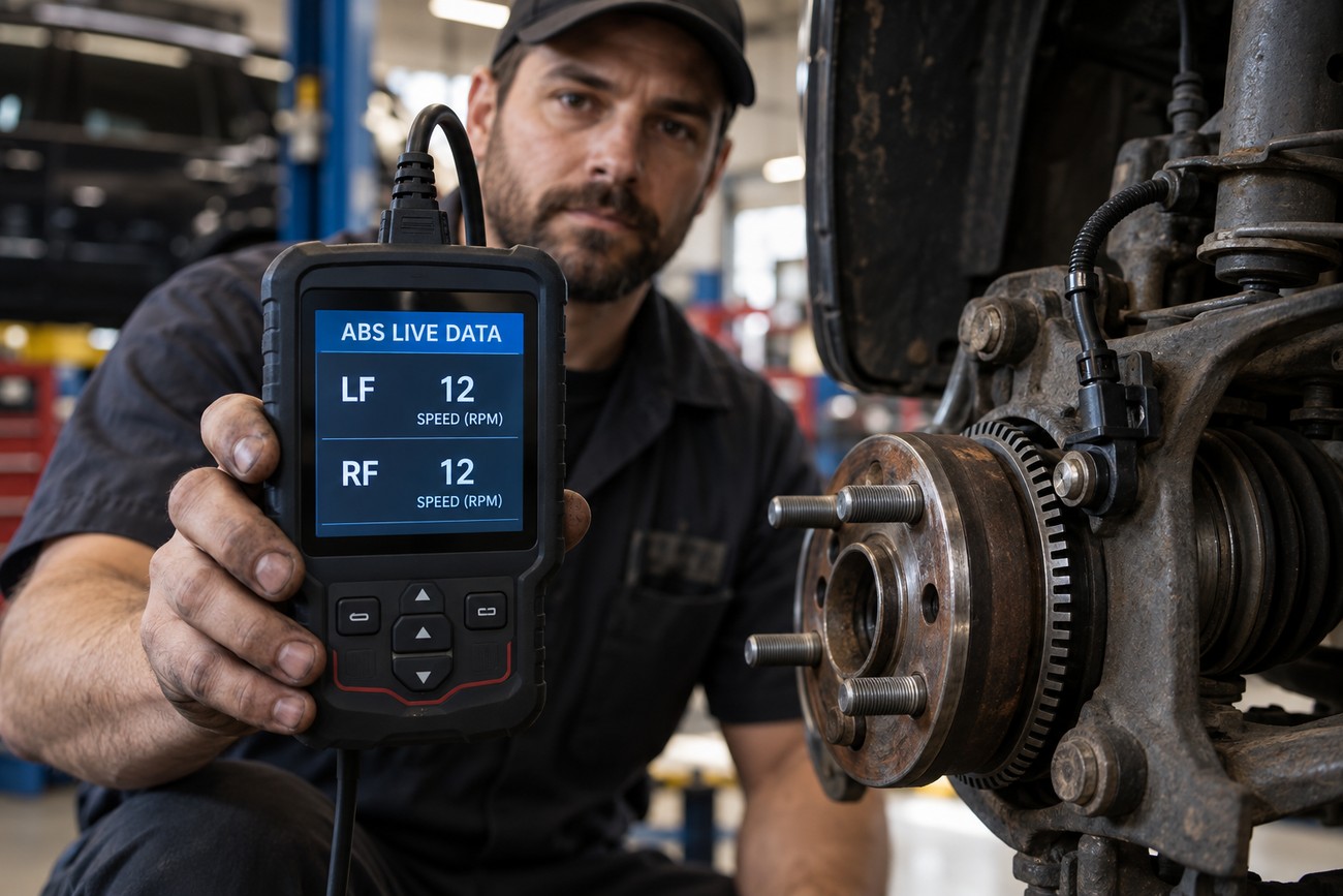
Read the returning code and review live wheel-speed data first. Recheck that the connector is fully seated and that no part of the lead has been pinched, stretched, or exposed to rubbing or heat. These checks can reveal an installation-related fault without disturbing the new sensor.
If the connection and routing are sound, inspect the encoder ring and hub bearing where the design allows. Periodic signal dropouts can indicate encoder damage or incorrect sensor positioning. A damaged encoder integrated into a hub will not be repaired by fitting another separate sensor.
Continue with the circuit tests specified for the vehicle and sensor type. A defective replacement sensor is possible, but wiring, connector corrosion, a bearing or encoder fault, and, less commonly, an ABS control fault can also explain the warning. Test the circuit and signal before deciding which part needs attention next.
Frequently asked questions
Repair cost depends on the vehicle’s design and what inspection reveals. A quote should show which part is being replaced and what work is included, especially if corrosion or hub damage is suspected. An estimate made before diagnosis may need to change if the sensor cannot be removed intact.
How much does it cost to replace a bad wheel speed sensor?
A firm price requires a vehicle-specific estimate and local labor rates. When comparing quotes, check whether the part is a separate sensor or a hub assembly, how much access labor is included, and whether diagnostic time is charged separately. Ask how the shop would handle a seized sensor or corroded fastener: extraction and possible hub work can substantially increase the final cost.