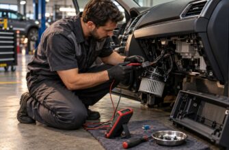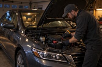

A dead speedometer creates immediate uncertainty about legal driving, speed limits, and whether the vehicle can be trusted. In many jurisdictions, a failed speedometer may be treated as defective required equipment, so driving should generally be limited to the nearest suitable repair facility. GPS speed can help estimate road speed, but it is not a legal substitute for the vehicle’s speedometer and can have delay and accuracy limitations.
The visible symptom can come from a mechanical cable, a vehicle speed sensor, an ABS/ESP module, wiring, the instrument cluster, or a voltage problem. Replacing the sensor without testing the circuit often leaves the original fault untouched. The useful starting point is the vehicle’s age, the exact symptom, recent repairs, warning lights, and whether a measured signal reaches the cluster or vehicle network.
- What to Do When the Speedometer Stops Working
- How Your Vehicle Generates the Speed Signal
- Speedometer Symptoms and the First Place to Test
- A Diagnostic Sequence That Avoids Guesswork
- Repair Paths for Cable, Sensor, ABS, and Cluster Faults
- Why Speedometer Repairs Fail the First Time
- Frequently asked questions
- How much does it cost to fix a speedometer?
- Why would my speedometer stop working all of a sudden?
What to Do When the Speedometer Stops Working
If the needle suddenly falls to zero, avoid treating the vehicle as fully roadworthy until the fault is checked. In many jurisdictions, a nonworking speedometer may be treated as defective speed-measuring equipment. Limit driving to the nearest appropriate service facility, and use a tow truck if the route would require extended driving or high-speed traffic.
GPS speed is useful as a temporary reference, especially for avoiding large speed errors, but it does not replace the vehicle’s speedometer. GPS readings can lag during acceleration or braking, and accuracy can vary with signal conditions, road layout, and the device itself. They also do not restore the vehicle’s required equipment.
Record what failed at the same time. A shared speed-signal problem may also stop the odometer and cruise control or trigger Check Engine, ABS, or ESP warnings. If only the speedometer fails while the odometer continues to count, the problem may be inside the gauge or its input stage; if several systems fail together, the source is more likely upstream in the sensor, ABS system, network, or power supply.
Do not clear warning codes before recording them. Note whether the fault appeared after a pothole, water exposure, battery problem, wheel or transmission work, ECU programming, or instrument-cluster replacement. These details can save diagnostic time because an intermittent speed signal may disappear while the vehicle is stationary in a workshop.
How Your Vehicle Generates the Speed Signal

Older vehicles commonly use a mechanical cable and plastic drive to connect the transmission to the speedometer. The transmission-side drive turns the cable, and the cable moves the mechanism in the instrument cluster. A worn cable may break, slip, bind, or create jumping and inaccurate readings before it fails completely.
Modern vehicles commonly use a vehicle speed sensor mounted at the transmission or differential. Depending on the design, the sensor produces an electrical signal that is read by the engine computer, body or comfort-control module, or instrument cluster. On some models, the signal passes through one or more control modules before it reaches the gauge, so a sensor can test correctly while the displayed speed remains absent.
On some CAN-equipped vehicles, ABS/ESP calculates or distributes the speed signal instead of using a separate standalone VSS. Wheel-speed sensors provide the raw information, and the ABS/ESP module sends vehicle-speed data across the vehicle network. A working-looking sensor therefore does not prove that the ABS module, wiring, network communication, and cluster input are healthy.
Vehicle architecture varies by model. Some systems route speed data through the engine computer, while others use a body or comfort-control module as an intermediary. This is why a generic scan of only the engine module can miss the relevant fault, particularly when the speed source is in ABS/ESP or the body network.
Speedometer Symptoms and the First Place to Test
Symptom timing often narrows the fault before any parts are purchased. A needle that drops to zero over bumps points toward a loose connector, poor ground, or damaged wiring as well as a sensor fault. A reading that becomes unstable after wheel, hub, transmission, ECU, or cluster work deserves inspection of the recently disturbed components and harnesses first.
| Symptom | Likely system areas | Next diagnostic check |
|---|---|---|
| Complete speedometer failure | Sensor circuit, ABS/ESP source, cluster input, power, or ground | Perform a full-module scan and check whether any control module sees vehicle speed |
| Speed drops to zero over bumps | Connector, ground, harness, or an intermittently failing sensor | Inspect and gently flex accessible wiring while monitoring the live speed signal |
| Needle fluctuates by approximately 20–30 km/h | Unstable signal, cable slip, wiring trouble, or calibration error | Compare live data with the cluster reading and test the signal under controlled conditions |
| Speedometer and odometer both stop | Shared speed-signal path or cluster input | Identify the source module and check signal delivery to the cluster |
| Failure begins after transmission or hub work | Damaged drive, disturbed connector, wheel-speed sensor, or harness | Inspect the serviced area before replacing the sensor or cluster |
| Speed is consistently inaccurate | Tire-size change, configuration, calibration, or a distorted signal | Verify tire size and coding, then compare measured and displayed speed |
A needle that fluctuates by approximately 20–30 km/h may indicate an unstable signal, cable slip, wiring trouble, or calibration error. This is different from a completely missing signal. The first task is to determine whether the sensor or module is sending an incorrect value, whether the cluster is misreading a correct value, or whether the vehicle configuration no longer matches the tires.
A dead odometer together with a dead speedometer suggests a shared speed-signal or cluster-input problem. Different tire sizes or incorrect ECU and cluster configuration can change displayed speed without proving that the speed sensor itself has failed. A vehicle that received different wheels, an ECU replacement, or software work may need configuration checks before component replacement.
A Diagnostic Sequence That Avoids Guesswork
Begin by confirming the symptom under safe conditions and recording all warning lights. Check whether live data in the engine, ABS/ESP, or body module shows vehicle speed while the gauge remains at zero. This distinction separates a missing source signal from a communication, cluster, or calibration problem.
Use a full-module scan rather than reading only the engine computer. VSS, ABS, wheel-speed, network, and cluster faults may be stored in different modules. A fault code identifies a circuit or system area to test; it does not automatically prove that the named sensor is defective.
Check the actual speed signal at the sensor and again at the cluster or network endpoint before condemning an ABS module, ECU, or instrument panel. Intermittent faults can disappear during a superficial stationary test.
Next, inspect fuses, module power supplies, battery condition, charging voltage, and grounds. Corrosion, poor grounds, and bad connector contacts are frequent causes of instrument-cluster signal loss, especially on vehicles older than 10–15 years. A weak battery, charging problem, voltage drop, or poor ground can also cause intermittent electronic speedometer behavior.
Inspect connectors and the harness at model-specific weak points, including flex areas in a wheel arch, the sill, under-seat sections, and locations exposed to water or road salt. Look for pushed-back terminals, green corrosion, broken insulation, and conductors that open when the harness moves. If the fault appears after bumps, a static visual inspection may not be enough.
Only after these checks should you measure the signal. A multimeter may confirm power, ground, resistance, or a basic switching signal, while an oscilloscope can reveal dropouts, distortion, and unstable amplitude. Follow the wiring diagram and the manufacturer’s test method because sensor circuits and network signals differ substantially between vehicles.
Repair Paths for Cable, Sensor, ABS, and Cluster Faults
On mechanical systems, cable or transmission-side plastic-drive failure is more common than failure of the cluster mechanism itself. A cable can break, slip, or bind intermittently, producing a jumping or incorrect reading rather than only a complete failure. The transmission-side plastic drive may be cracked or worn, and incorrect installation can damage it further.
Repair normally involves replacing the damaged cable or drive after confirming that the transmission fitting and cluster connection are sound. A replacement cable or non-original part must match the vehicle and be routed without sharp bends or binding. If a new cable immediately produces noise or a wavering needle, installation and the transmission-side drive deserve another inspection.
Electronic repairs depend on where the signal disappears. A faulty sensor may need replacement, while a damaged connector, corroded terminal, broken harness conductor, ABS/ESP fault, ECU or body-module configuration problem, or network issue requires a different repair. Replacing the VSS will not restore a signal that is being lost at a ground connection or inside the ABS system.
Some instrument clusters have damaged solder joints, connectors, or circuit traces that can be repaired instead of replacing the complete unit. A used cluster may require compatibility verification, CAN or software matching, coding, and adaptation. Installing a random used panel can create additional warning lights, communication faults, or odometer and configuration problems.
Why Speedometer Repairs Fail the First Time
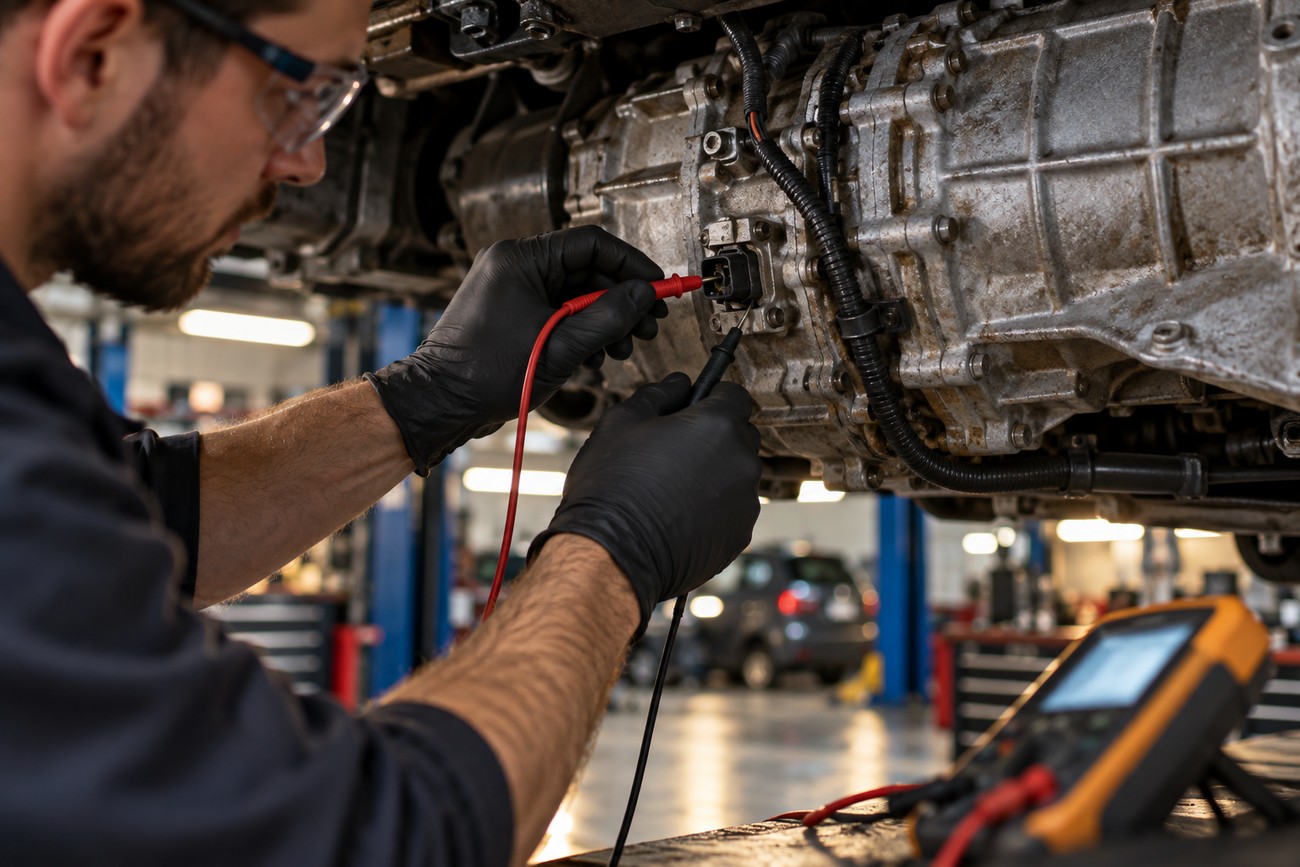
The most common failed repair is a parts swap based only on a fault code or a general symptom. Replacing a speed sensor without checking its power, ground, wiring, and output signal often leaves the original fault untouched. Cheap aftermarket sensors can also produce unstable or incorrect signals, making the vehicle appear to have a second problem.
Voltage problems are easy to miss because the vehicle may start and run normally. A weak battery, charging fault, voltage drop, or poor ground can affect the cluster and network intermittently. Checking system voltage under relevant operating conditions is more useful than assuming that a recently started engine proves the electrical supply is healthy.
ECU replacement or reprogramming without transferring the correct configuration can disrupt speed calibration or signal routing. Tire-size changes can create a genuine displayed-speed error without a failed sensor. On some Japanese vehicles, an instrument-cluster diagnostic mode can test the gauge without removing the cluster, but the procedure is model-specific and does not replace circuit testing.
A factory speedometer may read slightly high, while a faulty system can read low, increasing the risk of unintentionally exceeding the limit. A history of odometer alteration can also be associated with difficult-to-prove intermittent speed and cluster problems. In that situation, a complete module scan, wiring inspection, and configuration review are safer than fitting another used cluster by trial and error.
Frequently asked questions
How much does it cost to fix a speedometer?
The cost depends on the fault category: a mechanical cable or plastic drive, a sensor, wiring or ground repair, module programming, ABS/ESP work, or instrument-cluster repair involve different parts and labor. A connector repair may be relatively contained, while an ABS module or cluster may require diagnosis, coding, or specialist electronic repair before the final price is known.
Request an itemized diagnosis before authorizing replacement. It should state which module or circuit failed, whether power and ground were tested, whether the signal was measured, and whether programming or adaptation is required. This prevents paying for repeated sensors or a used cluster when the actual defect is a harness, configuration, or voltage problem.
Why would my speedometer stop working all of a sudden?
A sudden failure can follow water intrusion, a weak-voltage event, recent hub or transmission work, ECU programming, or movement of a damaged harness conductor. A connector may lose contact over a bump, or a partially broken wire may open only when the suspension or body moves. If the odometer, cruise control, ABS, or Check Engine warning changed at the same time, inspect the shared speed-signal path.
The timing of the failure is useful evidence. After wheel or hub work, inspect the relevant wheel-speed sensor and harness; after transmission work, inspect the drive, sensor connector, and transmission wiring; after ECU or cluster work, verify coding and network configuration. If the battery or charging system was recently weak, test voltage and grounds before condemning the speed sensor.