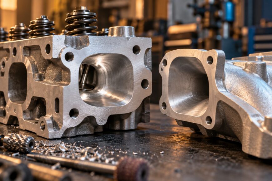
Port matching is often treated as a simple gasket-tracing exercise: place the gasket on the head, open every passage to its outline, and call the job finished. That approach can enlarge the entrance beyond what the manifold and engine actually need. Excessive cross-sectional area lowers mixture speed, which can weaken low-rpm response and leave a street engine less effective even if the port looks more impressive.
Useful cylinder-head porting is controlled correction of shape. The important areas include the port entrance, bowl, short-side radius, valve-seat transition, and valve-guide boss. Each cut should serve the path from the manifold to the valve, preserve adequate wall thickness, and suit the engine’s operating range. Maximum metal removal is rarely a sound objective.
The practical method is conservative: establish the real mating geometry, measure before cutting, remove small amounts, and check the result repeatedly. A flow bench adds valuable evidence, but good geometry, symmetry, and durability still begin with disciplined machining decisions.
- Why Bigger Ports Do Not Automatically Make More Power
- What Port Matching Actually Means
- The Port Shapes That Matter Inside the Head
- A Controlled Porting Workflow Without Guesswork
- Valve Seats, Surface Finish, and Durability Checks
- Common Porting Mistakes and Realistic Expectations
- Frequently asked questions
- How much horsepower does port matching add?
- How do you port match a cylinder head and intake manifold?
- How much HP do you gain from porting heads?
Why Bigger Ports Do Not Automatically Make More Power
Port matching means bringing the cylinder-head and manifold passages into sensible alignment at their joint. It does not mean making every opening as large as the gasket. The gasket is a sealing component, and its edge may be larger than the useful air path or may sit slightly off-center during assembly. Copying that outline without checking the parts can create an oversize entrance.
Cross-sectional area has to be considered alongside airspeed and engine rpm. A high-rpm engine can benefit from a passage that supports greater volume, while a street engine often depends on mixture velocity for throttle response and cylinder filling at lower speeds. If the port becomes too large for the engine, the mixture slows and the engine may feel softer even though the port has more volume.
This is why a larger port can produce little gain, or even make a street combination weaker. The problem is usually not that the engine has too much theoretical capacity; it is that the enlarged passage no longer maintains useful velocity through the operating range. Shape, valve size, camshaft, displacement, manifold design, and rpm range all influence the correct compromise.
A moderate result around 5–10% may be possible in a suitable application, but that is an expectation range rather than a promise. The result depends heavily on the original casting, the valve and seat work, the manifold, the rest of the engine, and the quality of the machining. A port that is opened dramatically for visual effect can deliver less useful airflow than a smaller port with better transitions.
What Port Matching Actually Means
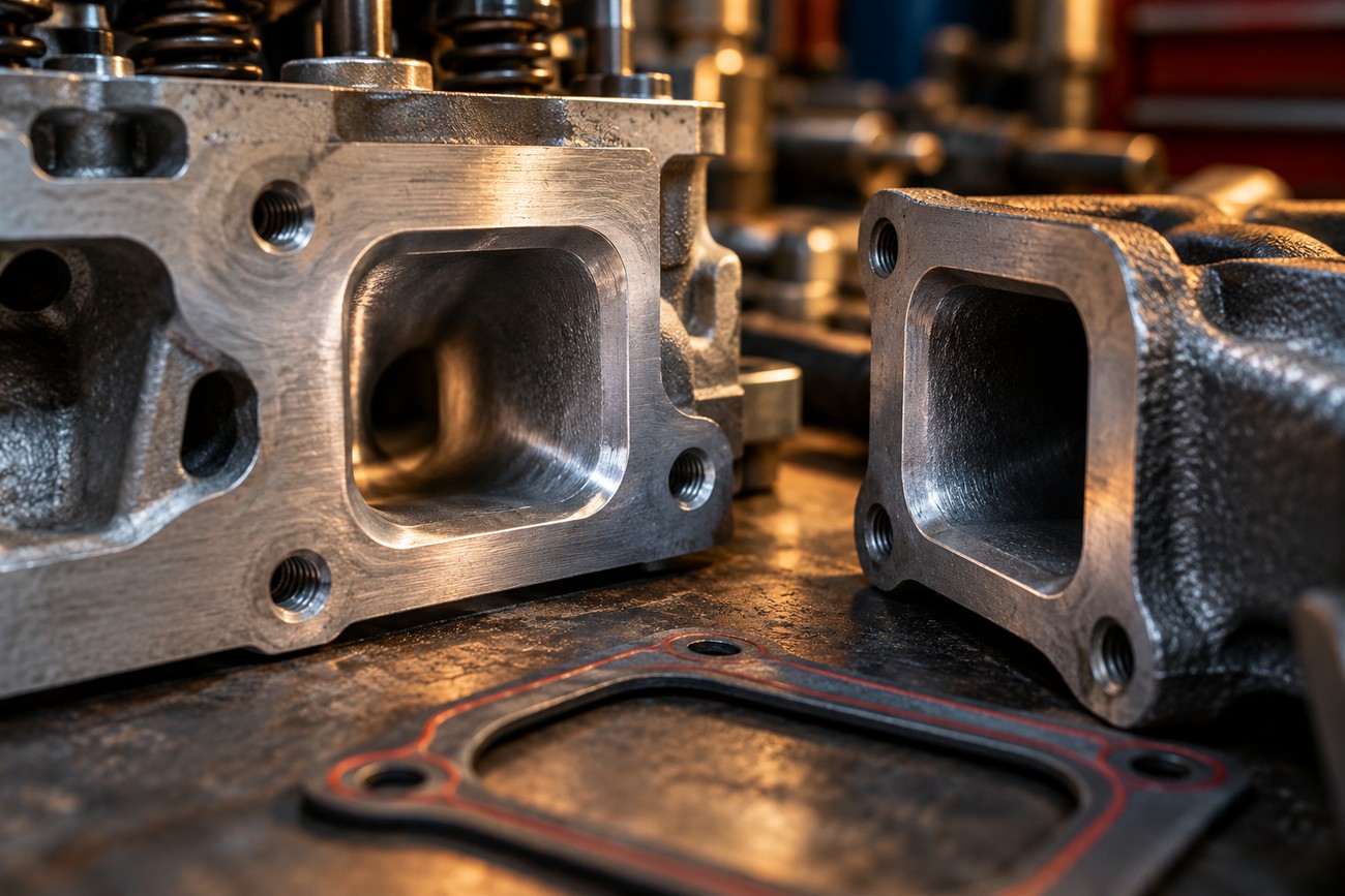
The working reference is the actual relationship between the cylinder-head entrance and the intake-manifold exit. Inspect both parts as a pair, check how they locate on the engine, and use the gasket only as part of that assembly information. A gasket outline by itself does not prove where the air passages should end.
In many combinations, the cylinder-head port entrance is made slightly larger than the manifold exit. Approximately 1/16 inch is used as a practical reference, creating a small step that avoids having the head wall project into the manifold passage. The exact amount remains application-dependent; the purpose is to prevent an abrupt obstruction without turning the head entrance into a large open cavity.
Begin with clean, assembled components whenever possible. Identify the bolt and locating-pin position, inspect the transfer marks, and verify that the gasket has not shifted from its installed position. Mark the actual mismatch on the head or manifold, then remove only the material needed to create a smooth transition.
After each small cut, clean the part and recheck it against the mating component. A second inspection often shows that the first mark was influenced by gasket movement or casting irregularity. The finished entrance should blend into the port rather than form a sudden expansion, and its shape should remain consistent from one cylinder to the next.
The Port Shapes That Matter Inside the Head
The port entrance is only the beginning of the flow path. Inside the head, the bowl below the valve seat, the short-side radius, and the seat transition have a greater influence on useful flow than simply increasing the overall port volume. These areas control how the stream turns toward the valve and how much separation occurs around the short side.
The bowl should blend the seat into the surrounding port with a controlled contour. Casting flash, sharp steps, and abrupt changes can be removed, but the goal is a continuous shape rather than a large excavation. The short-side radius deserves particular restraint because aggressive cutting can flatten the turn, reduce flow quality, and leave a thin or fragile section of the casting.
A good port generally retains a slightly tapering profile along its length. An uneven small–large–small sequence creates unwanted expansion and contraction, even if each individual area appears smooth. The hand-finished surface can look excellent while the longitudinal geometry remains poor, which is one reason visual inspection alone is unreliable.
Protect the short-side radius and guide boss because the largest visible opening is rarely the best airflow target. A controlled taper usually gives the stream a more useful path than a dramatic enlargement followed by a sudden contraction.
The valve-guide boss may be streamlined carefully to reduce an unnecessary obstruction. That is different from shortening the valve guide or removing excessive support around it. The guide controls valve stability and survives substantial heat and load; weakening its support can create a durability problem that a flow test may not reveal immediately.
A Controlled Porting Workflow Without Guesswork
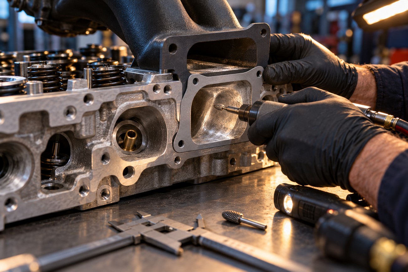
Start by inspecting the casting for core shift, thin areas, casting flash, and differences between cylinders. Establish the valve centerline, seat location, and guide position before deciding where material can be removed. The port should be understood in relation to the valve, not treated as an isolated tunnel.
Use the actual manifold and gasket to establish the entrance relationship. Mark the areas that interfere with the transition, then make small, controlled cuts with suitable tooling. Work progressively around the port instead of removing a large amount from one wall, and keep the manifold and head geometry coordinated throughout the process.
Repeated checks are essential. Measure critical sections where practical, compare corresponding ports, and monitor wall thickness near the short-side radius, guide boss, and roof. Symmetry does not mean forcing every casting to an identical shape when the original core positions differ; it means achieving consistent, purposeful geometry without creating a weak area.
A flow bench improves confidence because it allows before-and-after comparisons and reveals whether a change helped at relevant valve lifts. It cannot correct poor durability decisions or make an unsuitable port shape appropriate for the engine. Porting without measured testing is less predictable, rather than automatically invalid, so dimensional checks and conservative cuts become even more important.
The target is repeatable geometry, not a visually dramatic cavity. If a cut cannot be linked to a smoother transition, better valve approach, or corrected interference, it deserves skepticism. Removing metal simply because the tool is already in the port is a common way to trade useful velocity for volume.
Valve Seats, Surface Finish, and Durability Checks
Porting should not be treated as sanding alone. The valve-seat transition is a major part of the flow path, and at least a three-angle valve-seat treatment is a basic reference point for serious flow work. A beautifully blended bowl cannot compensate for a poor seat contour or an abrupt transition into the valve.
Surface finish depends on the application and the location. Carbureted intake ports are often left around 60–80 grit rather than mirror polished. A controlled texture can be preferable to a polished surface in this area, and mirror finish should not be treated as a universal airflow improvement.
Exhaust ports are commonly polished to discourage deposit adhesion and reduce heat retention. This does not make every exhaust passage identical, nor does it justify removing material indiscriminately. The finish should follow the geometry and the engine’s use, with particular care around the seat, guide area, and thin casting sections.
Inspect the head after machining for sharp edges, tool marks that create stress concentrations, and areas where wall thickness has become questionable. Protect the guide boss and retain sufficient guide support. Surface appearance is secondary to correct transitions, durable material thickness, and geometry suited to the engine.
Common Porting Mistakes and Realistic Expectations
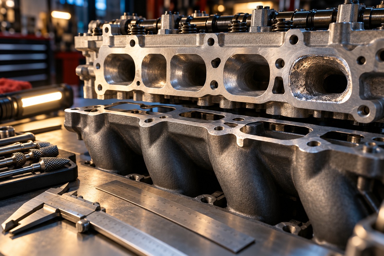
The most familiar mistake is matching the port to the gasket in the wrong place. Opening the head to a displaced or oversize gasket edge can enlarge the entrance beyond the manifold exit and create a poor transition. The correct reference is the assembled head-and-manifold relationship, with the gasket checked for position rather than copied blindly.
Another failure mode is widening the passage instead of improving its shape. A larger cross-section can reduce mixture speed and harm low-rpm response when it exceeds the engine’s needs. Street engines are especially vulnerable because they spend much of their operating life below the rpm range where a large port might offer an advantage.
Overworking the short-side radius, bowl, or guide boss can also reduce flow quality. Removing too much from the short side may damage the turn, while excessive work around the guide can weaken the casting or reduce valve support. Small, gradual cuts leave room for correction; aggressive cuts remove that option permanently.
Polishing everything is a poor substitute for seat and bowl work. Porting alone may deliver only a moderate result, commonly cited around 5–10% when the work is appropriate, and it may deliver less or even hurt performance when the geometry is wrong. Before-and-after flow testing, dyno comparisons, or controlled track testing are more useful than judging the job by shine, port volume, or internet horsepower claims.
Frequently asked questions
These questions address the decisions that are hardest to judge from photographs or general porting advice. The useful answer usually depends on the complete engine combination and on separating one machining change from the rest of the build.
How much horsepower does port matching add?
There is no fixed horsepower figure for port matching. The result depends on the original mismatch, the manifold and head design, the engine’s rpm range, and whether the work also includes the valve seats, bowl, and short-side radius.
A moderate result around 5–10% may be possible in a suitable application, but that figure is not a guarantee and should not be assigned solely to gasket matching. Comparable dyno tests are more meaningful: use the same engine, fuel, timing, manifold, exhaust, and test method before and after the change. Internet estimates usually combine different combinations and cannot isolate the effect of the port work.
How do you port match a cylinder head and intake manifold?
Assemble the head, manifold, and gasket in their installed position, using the bolts and locating features that control alignment. Inspect the actual interface from both sides, mark the genuine mismatch, and confirm that the gasket has not moved or been displaced before cutting.
Remove only the material needed to create a smooth transition, commonly leaving the head entrance slightly larger than the manifold exit, with approximately 1/16 inch used as a practical reference. Clean and recheck the parts after each stage, then verify that the entrance blends into the internal port without an abrupt step.
How much HP do you gain from porting heads?
Head porting can produce a moderate gain, but there is no universal horsepower number. The outcome depends on the casting, valve size, seat design, camshaft, displacement, manifold, exhaust system, and the engine’s intended rpm range.
Porting that improves the bowl, seat transition, and short-side radius can be more valuable than simply enlarging the passage. A street engine may lose response if maximum cross-sectional area is prioritized over velocity, so the correct result may be a carefully shaped port that looks less dramatic than an aggressively enlarged one.