A manual boost controller is simpler and usually cheaper. An electronic unit can hold boost more consistently as temperature, altitude, and load change, but neither device replaces proper ECU calibration. The controller changes how the wastegate is controlled; it does not automatically provide the fuel or ignition changes required by higher boost.
The practical decision is therefore larger than mechanical simplicity versus electronic sophistication. Boost spikes, changing weather, incorrect hose routing, and worn wastegate hardware can make a manual setup unpredictable, while a poorly configured electronic controller can add delay or overshoot. Installation, sensors, wiring, solenoids, and tuning also make the real cost higher than the price on the box.
- How Boost Control Works—and Why the Choice Matters
- Manual vs. Electronic Boost Controllers: What Actually Changes
- Manual Boost Controllers: The Appeal and the Trade-Off
- Electronic Boost Controllers: Stability, Control, and Complexity
- Installation Mistakes and Hidden Failure Modes
- Which Boost Controller Fits Your Car and Use Case?
- Frequently asked questions
- What does a manual boost controller do?
- How can I tell whether a boost spike is caused by the controller or the wastegate system?
How Boost Control Works—and Why the Choice Matters
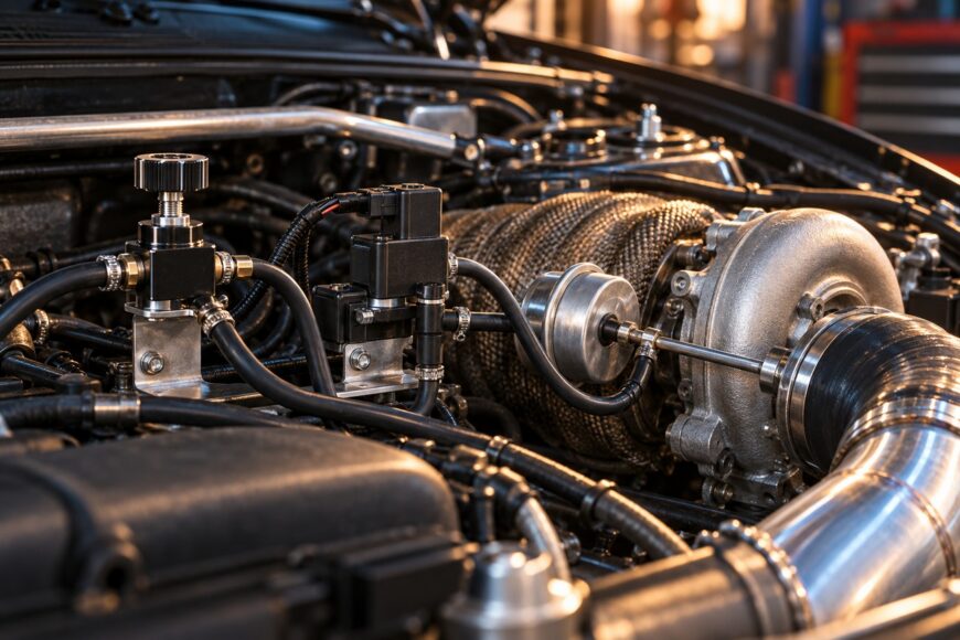
A turbocharger produces boost by using exhaust energy to drive the turbine. The wastegate limits turbine speed by opening a bypass path, and its actuator responds to a pressure signal. A boost controller alters that signal, usually by restricting or bleeding pressure before it reaches the actuator, so the wastegate opens at a different point.
A manual controller uses a mechanical valve and an adjustment screw or knob. An electronic controller uses a solenoid, with the ECU or a separate control unit varying solenoid duty cycle according to a target, operating mode, and feedback signal. In both cases, the turbocharger, wastegate, actuator, hoses, and calibration still determine how the system behaves.
Most factory-turbocharged vehicles use an ECU-controlled solenoid under OBD-II and emissions requirements; manual controllers are uncommon in stock applications. Factory control can also coordinate boost with throttle position, torque limits, diagnostic routines, and protective strategies that a basic manual valve cannot reproduce.
Increasing boost changes cylinder pressure, combustion temperature, and the engine’s airflow demand. A boost controller does not automatically retune fuel or ignition, so raising pressure without adapting the ECU calibration can cause detonation, overheating, or an unsafe lean condition. The controller is one part of the system, not a substitute for engine calibration.
Manual vs. Electronic Boost Controllers: What Actually Changes
The figures below describe reported behavior rather than universal guarantees. A fair comparison requires the same turbocharger, wastegate, plumbing, actuator, sensors, fuel, and ECU calibration; changing several of these at once can make the controller appear responsible for a problem elsewhere.
| Factor | Manual controller | Electronic controller |
|---|---|---|
| Control method | Mechanical restriction or pressure bleed set by the user. | Solenoid duty cycle controlled by a unit or ECU strategy. |
| Adjustability | Quick, simple adjustment, usually with one mechanical setting. | Maps, modes, boost-by-gear strategies, and approximately 1–2% duty-cycle adjustment steps on capable systems. |
| Reported stability | Forum reports commonly describe approximately ±0.2–0.3 bar variation in comparable configurations. | Good systems are commonly reported at approximately ±0.05–0.1 bar in comparable configurations. |
| Installation | Fewer electrical connections, but hose routing and port orientation remain critical. | Requires wiring, a solenoid, pressure plumbing, and often sensor or ECU integration. |
| Protection functions | Usually no active overboost cut, data logging, or automatic compensation. | May support overboost cuts, map switching, and MAP, AFR, or EGT inputs. |
| Cost | Generally lower initial cost and fewer components. | Higher hardware, installation, and calibration cost. |
| Best fit | Limited adjustment on a known, mechanically sound setup. | Changing conditions, multiple boost levels, track use, and more demanding calibration. |
Simple manual controllers commonly operate around 1.5–2.0 bar absolute, equivalent to approximately 0.5–1.0 bar of boost. The usable range depends on the wastegate spring, actuator, turbocharger, plumbing, and control strategy, so the range should not be treated as a safe target for every engine.
Tuning communities commonly recommend electronic control when planned boost exceeds 1.0 bar. That is guidance rather than a universal engineering threshold. Engine design, fuel quality, turbocharger efficiency, and calibration quality matter more than one pressure number.
Manual Boost Controllers: The Appeal and the Trade-Off
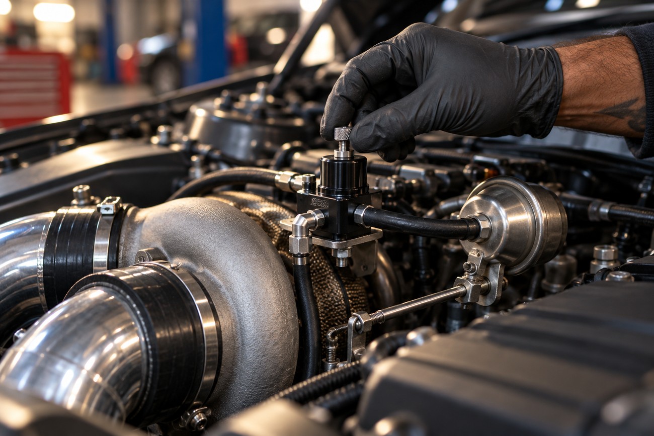
A manual controller is attractive because its operating principle is easy to understand and its installation can be inexpensive. Once the correct ports are identified, adjustment is immediate, with no menu structure, wiring harness, firmware, or control map. On a simple street setup with a known wastegate response, that directness can be useful.
Mechanical simplicity does not guarantee stable boost. Pressure can drift as intake temperature, ambient pressure, altitude, and engine load change. Hose condition, fittings, actuator preload, wastegate movement, and turbocharger behavior also influence the pressure signal, so a setting that looks acceptable in one test may behave differently later.
Users commonly report boost spikes and drift with inexpensive manual units, large turbochargers, or track use. Forum reports describe approximately ±0.2–0.3 bar variation in comparable configurations, although the result depends heavily on the complete hardware and calibration. A short pressure spike can be more damaging than a modestly lower steady-state boost level because the ECU and fuel system may not respond quickly enough.
Some manufacturers claim stable operation above 1.5 bar, but the available brief provides no independent long-term reliability data supporting that claim. A manual valve may work well on a carefully matched setup, yet it offers little ability to compensate for changing conditions or switch between fuel- and weather-specific targets.
Electronic Boost Controllers: Stability, Control, and Complexity
An electronic controller regulates a solenoid rather than relying on one fixed mechanical setting. Open-loop control establishes a base duty-cycle strategy, while closed-loop control uses boost feedback to correct toward a target. Capable systems can adjust duty cycle in approximately 1–2% steps, giving the calibrator finer control over spool, peak boost, and hold behavior.
Electronic control also supports several operating strategies. A car may use low, medium, and high boost modes, or change the target by gear, throttle position, fuel type, or operating condition. This flexibility is useful when the same vehicle must behave predictably on different roads, in different weather, or on fuel with different knock resistance.
Start closed-loop correction with a conservative open-loop duty map. Aggressive gain can chase a faster response while creating overshoot, and the controller then spends its time correcting a problem created by the base strategy.
Modern systems may accept MAP, AFR, and EGT data and provide overboost cuts or map switching. These functions can help limit risk when configured correctly, but they depend on suitable sensors, sensible thresholds, and a calibration that understands how quickly the engine and turbocharger respond.
Complexity is the main trade-off. Excessive gain can produce spikes, while overly cautious settings can make boost arrive later than expected. Cheap no-name hardware may suffer from display freezes, solenoid failures, false protection events, or compatibility problems with the vehicle’s CAN network and diagnostic systems.
Installation Mistakes and Hidden Failure Modes
Begin diagnosis with the pressure path, not the controller’s brand or adjustment range. Reversed ports, an incorrect T-fitting, a leaking connection, or a long, soft vacuum hose can delay the signal reaching the actuator. That delay may produce unstable control or a spike even when the controller itself is functioning correctly.
Inspect hose routing for unnecessary length, sharp bends, heat damage, and loose connections. Compare the controller’s pressure reading with a known-good gauge or fast-response MAP sensor where possible. A disagreement between sensors can lead to a false diagnosis and an incorrect electronic gain or duty-cycle change.
The wastegate system needs its own checks. Confirm that the actuator moves through its range, the rod is not binding, the wastegate seats correctly, and the spring and preload match the intended setup. A weak actuator, sticking flap, damaged diaphragm, or exhaust-side restriction can look like a controller fault because both problems may appear as overshoot, creep, or poor boost holding.
Running a manual controller alongside active factory electronic boost control can create conflicting control inputs. Unless one control loop is fully and correctly disabled, each system may alter the pressure signal without knowing what the other is attempting to achieve. Electronic systems can also require careful wiring and integration to avoid diagnostic faults or CAN-related conflicts.
Higher boost without revised fuel and ignition calibration can cause detonation and overheating, regardless of controller type. The hidden budget may include a solenoid, wiring, sensors, installation time, dyno or road calibration, and repairs to old hoses or wastegate hardware. Modified boost control can also place a vehicle outside factory emissions or safety approvals in some regions.
Which Boost Controller Fits Your Car and Use Case?
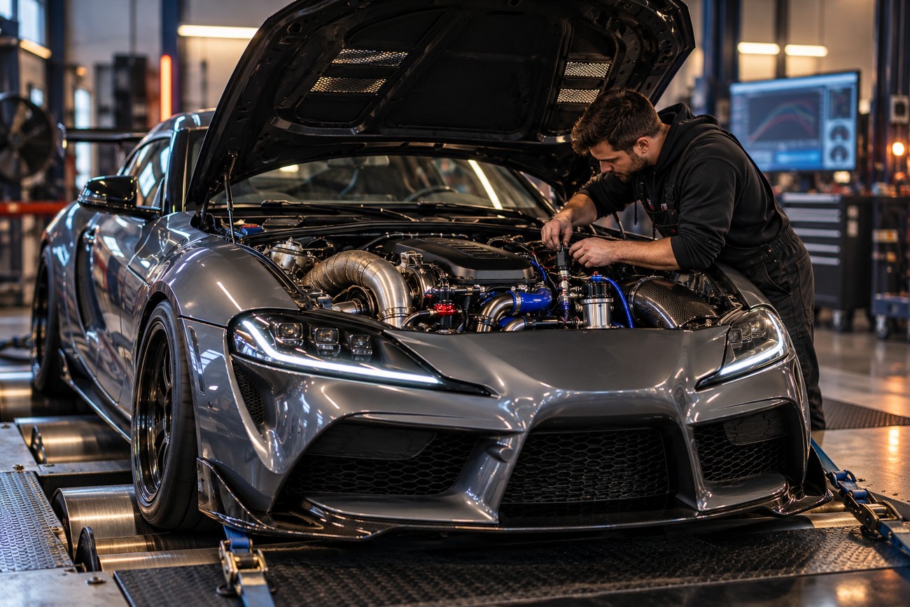
A manual unit is reasonable when adjustment is limited, the wastegate system is known to be healthy, and the vehicle will operate within a conservative, repeatable range. It can suit a simple setup where the owner accepts that weather and load changes may require verification. The ECU still needs calibration that matches the selected boost level.
Electronic control is the stronger choice for changing conditions, multiple boost levels, track use, or planned boost above 1.0 bar. That threshold is common tuner and forum guidance, not a universal engineering rule. The real advantage is the ability to define and monitor different targets rather than relying on one mechanical setting.
Choose based on the complete system rather than the controller alone. Check fuel delivery, cooling, exhaust flow, ignition components, hoses, sensors, actuator operation, wastegate behavior, and turbocharger condition before increasing pressure. A high-quality controller cannot compensate for a weak fuel pump, a leaking hose, or a wastegate that does not move correctly.
A safer sequence is to verify the mechanical system, establish conservative base boost, calibrate fuel and ignition in the ECU, and log pressure, air-fuel behavior, and knock-related data. Confirm the result under the loads and temperatures the vehicle will actually see. Add overboost limits and other protection strategies only after the base control is predictable.
Frequently asked questions
The answers below explain what each controller changes and where installation problems can arise. They also cover the relationship between boost control, wastegate operation, and ECU calibration. Use them alongside the system checks described above.
What does a manual boost controller do?
A manual boost controller changes the pressure signal reaching the wastegate actuator. In a common pressure-bleed or restriction design, the valve delays or reduces the pressure applied to the actuator, allowing the turbocharger to build more boost before the wastegate opens.
The wastegate actuator still works from its spring-loaded baseline, and the controller changes the opening point around that baseline. It does not command the ECU’s fuel or ignition maps, so any increase in boost must be matched with suitable engine calibration and supporting checks.
How can I tell whether a boost spike is caused by the controller or the wastegate system?
Use a staged diagnosis. First inspect hose routing, port orientation, T-fittings, and leaks; then verify the pressure reading against a known-good gauge or sensor. Test actuator movement and check that the wastegate is free, correctly preloaded, and able to close and open as intended.
Only after those checks should you replace or retune the controller. If the spike follows a change in duty cycle or valve setting while the mechanical system remains sound, control tuning becomes more likely. If it remains unchanged, investigate the actuator, wastegate, hoses, turbocharger, sensor signal, and ECU calibration.