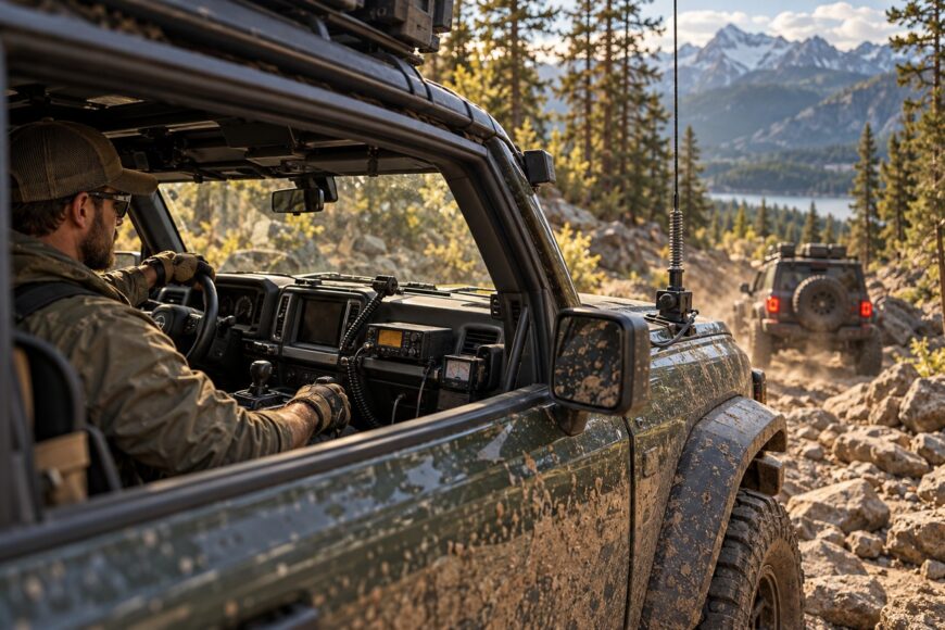
A CB radio can power on and still deliver little more than engine noise, weak range, or unreliable convoy communication once the vehicle enters forest, canyon country, mud, and rough terrain. The radio itself is often blamed first, although the real failure may be a poor RF ground, a damaged coaxial cable, an antenna hidden behind the body, or electrical interference from the vehicle.
An off-road installation balances two competing needs: a compact, protected setup that survives branches and vibration, and an antenna system with enough effective length and clear placement to communicate beyond the next vehicle. Placement, grounding, cable routing, and final testing usually matter more than advertised wattage. A well-installed legal radio with a suitable antenna is more useful on the trail than a powerful-looking unit connected to a compromised antenna system.
- Choose a CB Radio Setup That Fits the Trail
- Choose the Antenna, Mount, and Vehicle Location
- Mount the Radio and Build a Reliable Power Connection
- Route the Coax and Control Electrical Noise
- Set SWR in the Final Vehicle Configuration
- Test Range and Fix Common Off-Road Communication Failures
- Frequently asked questions
- How should I test a CB installation when two vehicles are available?
- Why can the same CB setup work on one vehicle but poorly on another?
- What should I do if SWR changes after trail damage or a hard impact?
Choose a CB Radio Setup That Fits the Trail
A suitable off-road CB system needs certified equipment, controls you can operate while seated and belted, and a microphone that remains clear over tire noise, engine vibration, and open windows. In the United States, CB uses 40 shared channels, and frequencies are not assigned to individual users. That means a convoy must manage channel use rather than expect a private frequency.
Compact radios are practical when dashboard space is limited or the vehicle is exposed to water, tools, and passengers. Some place the controls and speaker in the microphone, which allows the main unit to sit under a seat or behind the dash. A conventional radio may offer a more usable display, stronger speaker placement, or easier access to connections, but it needs a secure mount that will not become a knee hazard or rattle loose on rough ground.
The legal CB transmitter limit is 4 watts carrier power for AM and 12 watts PEP for SSB. FCC rules require certified and labeled CB equipment; internal modifications and power amplifiers are prohibited. Extra transmit power also cannot correct a short, poorly positioned antenna, a bad ground, or terrain that blocks the signal.
Choose a radio with a clear microphone, a useful channel display, and controls that do not require you to look away from a difficult trail section. A noise blanker or microphone gain control can help in particular conditions, but these features should be adjusted after the installation is electrically quiet. They should not be used to conceal an ignition fault, alternator noise, or microphone overload.
Choose the Antenna, Mount, and Vehicle Location
Antenna location has a greater practical effect than small differences between radio models. A higher, less-obstructed mount generally gives better results, while a low rear mount may be shielded by the body, spare tire, or cargo. A vehicle antenna has no separate FCC height limit equivalent to the 20- and 60-foot limits for fixed installations, though power-line safety and applicable local rules still apply.
| Option | Efficiency and clearance | Security and RF-ground needs | Best use |
|---|---|---|---|
| Roof or upper-body mount | Usually the clearest and most effective location; more exposed to branches. | Bolted mounting is mechanically secure when bonded to clean vehicle metal. | Regular trail use where antenna height and communication performance matter. |
| Rear bumper mount | Good trail clearance, but the body, spare tire, or cargo can shield the antenna. | Requires a strong mount and a dependable metallic RF ground through the vehicle structure. | Vehicles where upper mounting is impractical and clearance has priority. |
| Magnetic mount | Placement can be effective on a clear metal roof, but the cable and mount are exposed. | Convenient for temporary use; less mechanically and electrically predictable than a bolted mount. | Short-term installations, rental vehicles, or occasional trips. |
| Short flexible antenna | Offers branch clearance and flexibility, but is generally less efficient than a full-size quarter-wave antenna. | Still needs a sound mount and RF ground; flexibility does not solve poor placement. | Dense forest and technical trails where a longer antenna may catch branches. |
A full-size quarter-wave antenna is generally more efficient than a short antenna, but the longer element is more likely to catch branches and stress the mount or body. A magnetic base can also slide, lift on branches, scratch paint, or lose reliability on rough tracks. For a permanent installation, a bolted mount on properly bonded vehicle metal gives more predictable mechanical and electrical performance.
Do not treat a low SWR reading as proof that the antenna is well placed. The antenna may still be physically too short, hidden by the body, or radiating inefficiently in its chosen position. Paint, rust, sealant, and plastic panels can interrupt the RF connection even when the bracket appears firmly attached.
Mount the Radio and Build a Reliable Power Connection
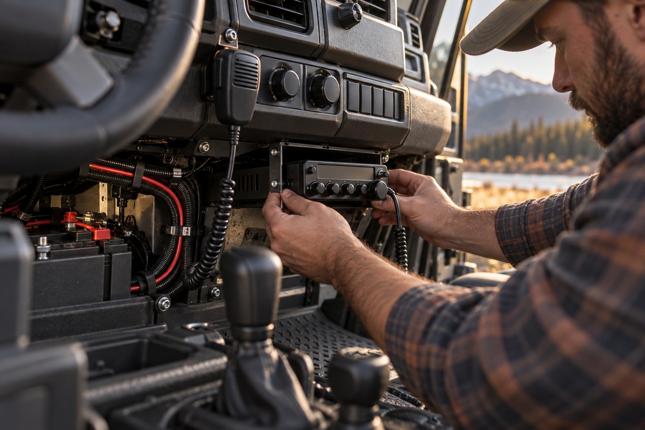
Mount the radio where the display and controls are visible without reaching across the steering wheel, and where the microphone can be released without snagging on recovery gear. Use a secure bracket and protect the cable from sharp edges and repeated movement. The fuse should be close to the power source and sized according to the radio manufacturer’s instructions.
A cigarette-lighter socket is convenient for a temporary test, but it can introduce voltage drop, unstable contact, electrical noise, or unexpected shutdowns. A dedicated fused power connection is usually more dependable for a permanent installation. Keep the power leads appropriately supported, and avoid routing them where tools, pedals, seat rails, or water can damage them.
The vehicle’s metal body is part of the antenna system, yet metal does not automatically mean a good RF ground. Paint, rust, sealant, plastic supports, and poor bonding can interrupt the connection. Where the mount depends on the body for RF continuity, expose suitable contact surfaces, protect them against corrosion after assembly, and verify the bonding rather than assuming it is adequate.
A weather-resistant radio housing does not make the microphone, speaker, connectors, or fuse holder waterproof. Seal exposed connections without trapping water inside them, provide a drip path where appropriate, and avoid mounting the radio where a roof leak or windshield wash can run directly into its controls. Protection should account for pressure washing, wet gear, and condensation, not only rain.
Route the Coax and Control Electrical Noise
Plan the coaxial route before tightening the antenna mount. Keep the cable away from sharp edges, allow a gentle service loop, and avoid crushing it beneath trim or against a bracket. A cable stretched across a door or hood hinge can suffer repeated bending and tension until the jacket or center conductor fails.
Route coax separately from ignition wiring, high-current power cables, inverters, and LED controllers where practical. These sources can put noise into the receiver, producing a rough hiss or repetitive whine that may be mistaken for a weak antenna. Do not coil excess coax tightly beside the radio, and do not use a damaged cable simply because its outer jacket still looks intact.
Coax, connectors, and the antenna form one RF system. Replacing the radio while leaving a crushed cable or poor connector in place changes the symptom more often than it changes the result.
Place the microphone where it faces the speaker’s mouth and is protected from direct tire spray and wind blast. A louder speaker cannot correct microphone overload, engine noise, or a microphone mounted beside a vibrating panel. Likewise, a microphone amplifier may add distortion when the original problem is excessive gain or an acoustically poor location.
Set SWR in the Final Vehicle Configuration
Inspect the connectors, braid, center conductor, and coax jacket before making any adjustment. Confirm that the antenna is installed in its actual trail position, that the mount is tight, and that the RF contact does not depend on a painted or contaminated surface. A high SWR can indicate an installation error, poor RF ground, damaged coax, bad connectors, or incorrect antenna adjustment.
Make the measurement with the final cable route in place and the vehicle doors closed. The antenna should be mounted as it will be used, rather than held beside the vehicle or tested on a workbench. Follow the antenna maker’s adjustment method, because some designs use a whip length, a tuning tip, or another specific adjustment.
Tuning an unfinished installation can send you after the wrong fault. Check braid contact, connectors, door position, coax condition, and the antenna mount before changing antenna length.
SWR measures matching among the transmitter, coax, and antenna; it is not a direct measurement of communication range. A low reading can coexist with body shielding, an inefficient short antenna, or an unfavorable mounting position. A 1:1 reading therefore does not guarantee maximum range or confirm that the antenna radiates efficiently.
After adjustment, key the radio only as long as needed for the test and avoid transmitting on an occupied channel. Recheck the system after trim panels are refitted or the antenna is moved. The final result should reflect the configuration used on the trail, including doors, cable routing, and the installed mount.
Test Range and Fix Common Off-Road Communication Failures
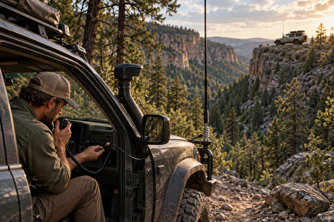
If the radio hears noise but few stations, first separate receiver noise from a lack of signals. Turn off or isolate accessories one at a time, check the microphone and speaker connections, and inspect the antenna system. If the radio hears nearby vehicles but cannot reach them, terrain, body shielding, antenna height, effective antenna length, coax loss, or the vehicle’s metallic ground may be limiting transmission.
Dense forest and canyon walls can sharply reduce practical range, and the effect may be asymmetric. One vehicle may hear another from a ridge while the return signal is blocked by a slope, a spare tire, or the position of the antenna. Marketing claims about long range often omit forest density, terrain, simultaneous traffic, and the shielding caused by the vehicle body.
A long antenna generally provides better efficiency, while a short flexible antenna offers better clearance in branches and tight terrain. Choose according to the route and protect the mount from repeated side loads. A long element that bends the bracket or strikes the body can leave the vehicle with worse communication than a shorter antenna that remains correctly positioned.
For a convoy, agree on a working channel and a backup channel before entering difficult terrain. All 40 CB channels are shared, so another group can be using either channel. Channel 19 is commonly used by highway drivers, but it is not officially reserved by the FCC for highways, off-road groups, or any specific community.
When diagnosing intermittent operation, watch for vibration-related faults: a loose fuse holder, a connector that opens when the dash flexes, or a coax cable pinched by a door. Carrying a spare fuse, a replacement microphone, and a short temporary cable can be more useful on a remote trail than adding an amplifier. Test the repair at a safe stopping point before relying on it in the next canyon or forest section.
Frequently asked questions
Field testing is more useful when it separates radio faults from antenna, vehicle, and terrain faults. Use the same test discipline after installation and after significant trail damage.
How should I test a CB installation when two vehicles are available?
Put the second vehicle at a known, safe distance with a clear line of travel, then exchange brief transmissions in both directions. Move one vehicle while keeping the other stationary, and repeat the test from a ridge, behind a slope, and in forest if those conditions represent the route. Record whether each vehicle can hear and reach the other; one-way communication points toward terrain, antenna placement, or vehicle-specific shielding rather than proving that the radio has failed.
Why can the same CB setup work on one vehicle but poorly on another?
Vehicle body shape, roof or bed material, bonding between panels, electronic accessories, and antenna clearance all change the RF environment. A setup that works on a clear metal roof may perform poorly beside a tall spare tire or behind a cargo body. Transfer the radio and antenna one component at a time, then compare the SWR and receive noise in each vehicle instead of judging the two installations from different locations.
What should I do if SWR changes after trail damage or a hard impact?
Stop transmitting until you inspect the antenna whip, spring, mount, connector, and coax jacket. Look for a bent bracket, a loose fastener, a cracked connector, a crushed section of cable, or a mount that has lost contact with clean vehicle metal. After correcting the physical fault, repeat the SWR check in the final vehicle configuration; a changed reading after an impact is a warning to find the mechanical cause, not an invitation to keep transmitting at full power.