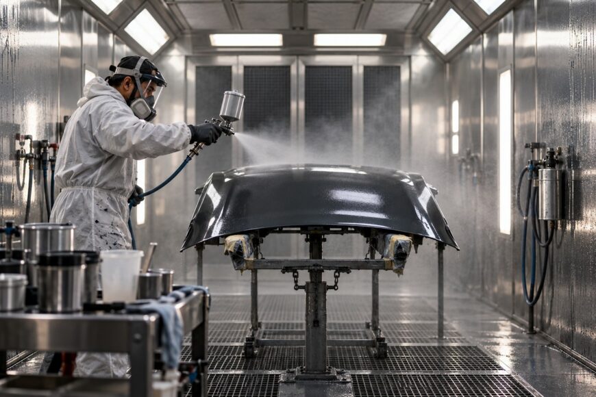
A paint job can consume far more material than an area-and-coverage calculation predicts. Overspray, material left in hoses, mixing and filtration losses, equipment cleaning, color changes, and rework are usually outside the simple estimate. The result is a familiar cost problem: the paint price looks acceptable until the finished-part cost is calculated.
Transfer efficiency (TE) connects spray performance with real cost. It measures how much coating solids reach the part, helping explain why two systems using the same paint can produce different material bills. A high advertised TE still requires caution: geometry, setup, operator technique, production speed, and equipment costs determine whether the claimed savings appear in the shop.
- What Transfer Efficiency Means in Paint Application
- How Transfer Efficiency Changes the Cost of a Finished Part
- Typical Transfer Efficiency by Application Method
- Why Advertised Transfer Efficiency Falls on Real Parts
- Choosing a Spray Method by Total Job Economics
- How to Improve Transfer Efficiency Without Creating Rework
- Frequently asked questions
- How much paint is wasted with an airless sprayer?
- How do you calculate transfer efficiency from a real paint job?
- What are the disadvantages of electrostatic painting?
What Transfer Efficiency Means in Paint Application
Transfer efficiency is the mass of coating solids deposited on the part divided by the mass of coating solids used, multiplied by 100%. In plain terms, it shows how much of the material intended for the job becomes part of the applied film. The remaining material may miss the part, remain in the system, or be removed during preparation and cleanup.
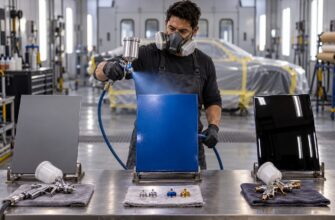
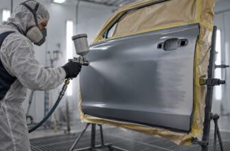
Material that does not deposit on the part is overspray. With a spray gun, some of the fan travels around the edges, falls short, or becomes airborne mist. Overspray is one component of total material loss, alongside mixing residue, filter waste, hose residue, flushing, cleaning, and coating discarded during color changes.
TE applies primarily to coating solids rather than simply to liters of liquid paint. Solvent or thinner evaporates, so two liquid mixtures with the same volume can leave different amounts of film. A useful comparison therefore starts with solids content and the dry film thickness required on the part.
This distinction prevents a common purchasing error. A shop may appear to use more liters after adding thinner, even though the relevant material for TE is the solids that remain after application. Conversely, a low-solids product can look economical by volume while requiring more liquid to build the required dry film.
How Transfer Efficiency Changes the Cost of a Finished Part
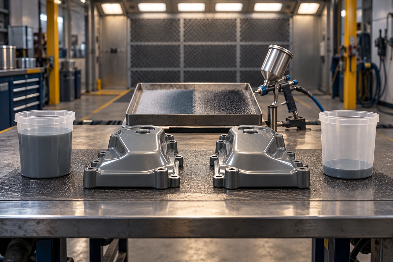
For purchasing, the basic relationship is: required coating quantity is approximately the coating solids that must remain on the part divided by TE. For the same dry film thickness, theoretical coating-solids consumption is inversely proportional to transfer efficiency. The calculation is useful for comparing methods, provided the actual job losses are added afterward.
At 35% TE, a process requires approximately 1.86 times as much coating solids as a process operating at 65% TE for the same deposited solids. The difference is larger than the percentage-point change suggests because the comparison uses the fraction retained, not the difference between the two TE figures.
The same logic applies to smaller improvements. Increasing TE from 35% to 45% reduces theoretical consumption by approximately 22% relative to the original consumption. That saving can be meaningful across a repeated production run, although it disappears if the new setup slows application or creates defects that require another pass.
Cost per finished part includes coating, thinner, energy, filters, cleaning, labor, disposal, equipment, maintenance, and rework. A system that uses less paint can still cost more if it needs a larger compressor, frequent servicing, slower preparation, or extra operator time. Job costing should therefore compare material used with acceptable finished output rather than multiplying a catalog price by a theoretical coverage figure.
Typical Transfer Efficiency by Application Method
The figures below are indicative ranges for particular processes and conditions. They are useful benchmarks, not guarantees for every coating, operator, part, or spray setup.
| Application method | Indicative TE | Strengths | Conditions and limitations |
|---|---|---|---|
| Conventional air-atomized spray | Approximately 25–50%; about 25% is an EPA air-atomized spray reference | Flexible equipment and familiar operation | Air pressure and atomization can create substantial mist; results depend heavily on technique and geometry |
| HVLP | Approximately 65–75%; up to 90% may be possible under suitable conditions | Lower atomizing velocity can reduce overspray and improve material retention | High air demand, pressure settings, nozzle choice, fan control, and operator technique affect the result |
| Electrostatic spray | Approximately 50–95%; automatic systems are associated with approximately 70–80% | Can improve deposition on suitable conductive, grounded parts | Performance falls in recesses, behind screens, and on poorly grounded parts; coating compatibility and safety controls matter |
| Flow or dip coating | Approximately 90% | High material utilization for suitable repeatable shapes | Requires compatible geometry, tanks or flow equipment, and control of drainage and coating buildup |
| Electrodeposition | Approximately 95% in industrial processes | High utilization and consistent coverage on compatible assemblies | Industrial equipment, chemistry control, and part requirements limit its use |
Why Advertised Transfer Efficiency Falls on Real Parts
Controlled-test results usually involve a defined gun, coating, distance, speed, panel, and film target. A real part may contain edges, grilles, tubes, small profiles, or recessed areas that intercept only part of the fan. The smaller or more irregular the part, the more material can travel beyond its contour, even when the spray technology itself is efficient.
Electrostatic spraying adds another set of conditions. The part must be suitably grounded, and the coating must have compatible conductivity. The electrical field may help around exposed surfaces while producing weak coverage inside corners, behind screens, or in other Faraday-cage areas.
A controlled fan and spray distance should follow the part contour rather than the lowest possible pressure. A narrower, deliberate pattern can reduce edge overspray on small profiles without forcing extra corrective passes.
Gun distance, fan width, overlap, travel speed, and nozzle selection influence consumption alongside pressure. Raising air pressure to increase speed can produce more atomization mist and overspray instead of a proportional productivity gain. A large fan may cover a panel efficiently while wasting material around a narrow tube or bracket.
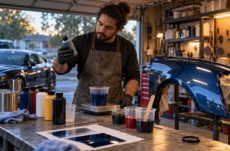
Advertised TE generally excludes losses from mixing, filtration, equipment cleaning, color changes, and material left in hoses. Those losses can be substantial in short runs or frequent color changes, where the coating used to prepare and flush the system is spread over relatively few finished parts.
Choosing a Spray Method by Total Job Economics
HVLP, airless, and electrostatic systems should be compared for the specific geometry, production volume, color, viscosity, and finish requirement. Airless can be economically preferable on large areas because its productivity reduces labor time, even when actual TE varies with pressure, tip selection, distance, and operator technique.
HVLP may suit controlled finishing work where overspray, appearance, and material retention matter. Its air demand can increase compressor energy and maintenance costs, and poor settings can erase the expected saving. Electrostatics may suit repeatable conductive parts, while additional controls and preparation can make the system difficult to justify for small or irregular batches.
Roller, brush, flow-coat, or dip coating may be more economical than spraying where geometry and appearance requirements allow. These methods can reduce airborne loss, although they bring their own limits in surface texture, access, drainage, thickness control, and production rate.
Some US requirements specify HVLP, electrostatic, or equivalent technology with at least 65% TE for particular spray operations. That threshold applies to specified categories of work; it is not a universal guarantee of finish quality, measured shop performance, or lowest cost. Compliance and economics still require a process check on the actual part.
How to Improve Transfer Efficiency Without Creating Rework
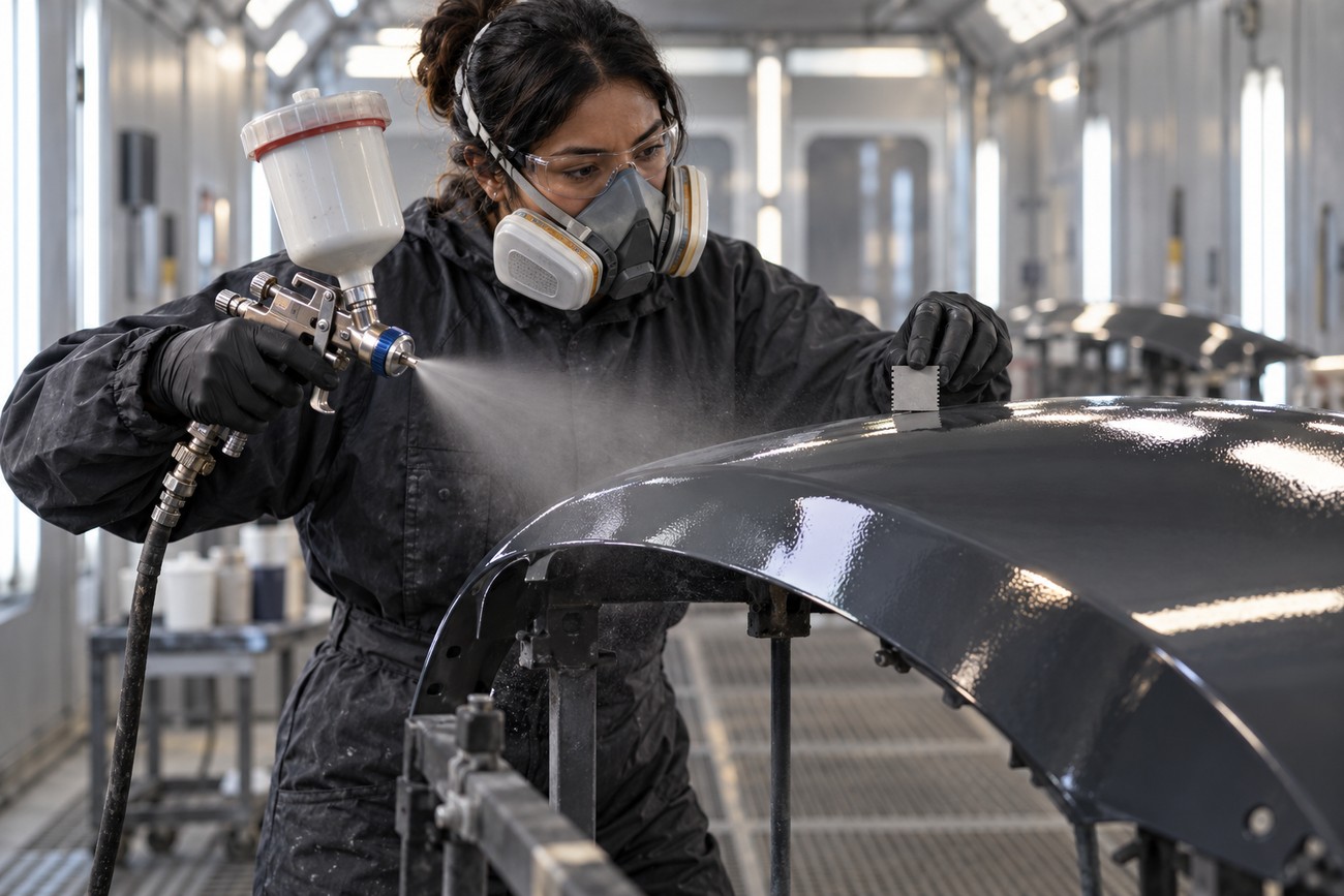
Start with the dry film target and solids content, then estimate the solids that must remain on the part. Select the application method according to shape, finish, volume, and coating viscosity. A small trial on a representative part is more informative than a maximum TE figure from a controlled test.
Test the gun with the intended nozzle, pressure, and material. Set the fan width for the part rather than leaving it at a universal setting. Control distance, travel speed, and overlap consistently; excessive distance promotes dry spray, while excessive overlap increases film build and consumption.
Where electrostatics are used, verify grounding and coating compatibility before judging the system. For every method, record material mixed, material remaining in the cup and hoses, cleaning material, and usable finished output. The resulting shop figure includes the losses that a spray-gun specification leaves out.
Higher TE has value only when it preserves coverage, finish quality, speed, and first-pass yield. Dry spray, orange peel, runs, missed areas, and repeated passes can erase the apparent paint saving. The practical test is cost per acceptable finished part, measured over a normal production cycle.
Frequently asked questions
Transfer efficiency is most useful when measured against actual material use and acceptable finished output. The following questions address common sources of waste, practical measurement, and the limits of electrostatic painting.
Results vary with the part, equipment, coating, and operator technique, so published figures should be treated as benchmarks rather than guarantees. Real job losses also include preparation, cleaning, and rework.
Comparing the complete process gives a more reliable result than comparing spray technology alone.
How much paint is wasted with an airless sprayer?
There is no universal waste percentage for airless spraying. Overspray depends on tip size, pressure, fan width, distance, coating viscosity, part geometry, and operator movement. Large flat areas can use airless efficiently because productivity is high, while edges, small parts, and poorly controlled spray patterns may create substantial loss.
Separate the losses before judging the method. Record paint used for priming the pump and filling the hose, material flushed during cleaning, residue left in the hose, overspray collected outside the part, and coating discarded after the job. This separates theoretical overspray from total job waste and produces a more useful cost per finished part.
How do you calculate transfer efficiency from a real paint job?
Measure the mass of coating solids actually used during application, then determine the mass of coating solids deposited on the part. TE is the deposited solids divided by the solids used, multiplied by 100%. Liquid volume alone is insufficient because thinner and solvent evaporate.
In a shop trial, weigh the mixed coating and record its solids content, then account for material remaining in the cup, hoses, filters, and cleaning system so it is not counted as coating solids used in application. Estimate or measure the coating solids added to the part from film thickness, coated area, and the product’s solids and density data. Repeat the measurement over several parts so one unusual setup does not define the process.
What are the disadvantages of electrostatic painting?
Electrostatic painting can struggle with Faraday-cage effects in corners, recesses, and areas behind screens. It also requires reliable grounding, suitable coating conductivity, and safety controls for the charged equipment and work area. Poor grounding can sharply reduce the expected deposition benefit.
The system adds equipment complexity and may require process controls that are difficult to justify for small, irregular, or frequently changing parts. Geometry shadowing can force manual touch-up, while coating compatibility and color changes add preparation time. Its economics improve when parts are repeatable and the electrical effect can be used consistently.