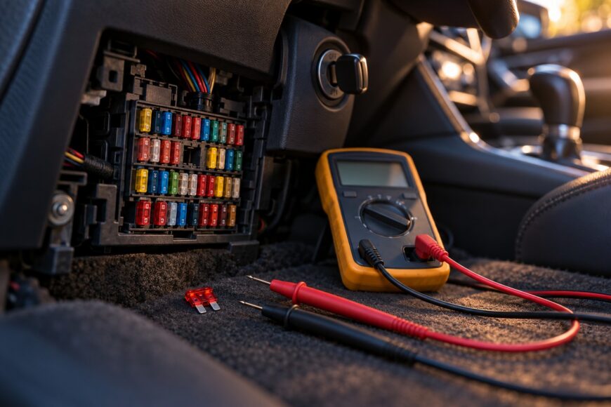
A fuse can look intact while the circuit remains dead, and a replacement can blow as soon as the equipment is switched on. A visual check is useful, but it cannot reliably reveal a microcrack, poor contact, or a fault in the fuse holder.
For an installed fuse, a test light or voltmeter can compare voltage at both accessible test points. For a removed fuse, a multimeter can check continuity or resistance, but only after the circuit is fully de-energized. The correct replacement must match the specified rating, type, and physical format, while any fuse that fails again needs diagnosis rather than a larger substitute.
- Start With Safety and the Right Test
- Find the Correct Fuse Before Testing or Buying
- How to Test an Installed Fuse With Voltage
- How to Test a Removed Fuse With a Multimeter
- Replace the Fuse Without Defeating the Protection
- If the New Fuse Blows Again, Stop Replacing It
- When the Fuse Is Not the Real Problem
- Frequently asked questions
- What is the 80% rule for fuses?
- Why does a fuse have a voltage rating if the circuit voltage is lower?
- How can I test whether a fuse is blown?
- How do I test and replace a blown fuse with a multimeter?
Start With Safety and the Right Test
Basic fuse testing is appropriate for accessible, low-voltage vehicle circuits when you can identify the fuse and follow the vehicle’s service information. Switch off the ignition and electrical loads before removing a fuse, where the vehicle procedure allows. Some systems store settings or require a specific shutdown sequence, so the owner’s manual takes priority.
Resistance and continuity tests require a dead circuit. Remove the fuse, confirm that the circuit is not powered, and only then connect the multimeter in resistance or continuity mode. An ohmmeter must not be connected to a powered circuit because the meter can be damaged and the reading can be meaningless.
A voltage test is different: it is performed on an energized circuit with the fuse installed. Use only the test points and meter range suitable for the vehicle’s low-voltage system, and avoid probing connectors or terminals that are difficult to control. A short from the probe tip can damage wiring or electronic modules.
Main fuses, battery-mounted high-current fuses, pyrotechnic fuse assemblies, and high-voltage fuses in hybrid or electric vehicles are outside a routine DIY procedure. They may require a separate manufacturer procedure, protective equipment, isolation checks, and qualified service. Stop if the fuse is part of a high-energy assembly or if the service information does not clearly describe safe removal.
Find the Correct Fuse Before Testing or Buying
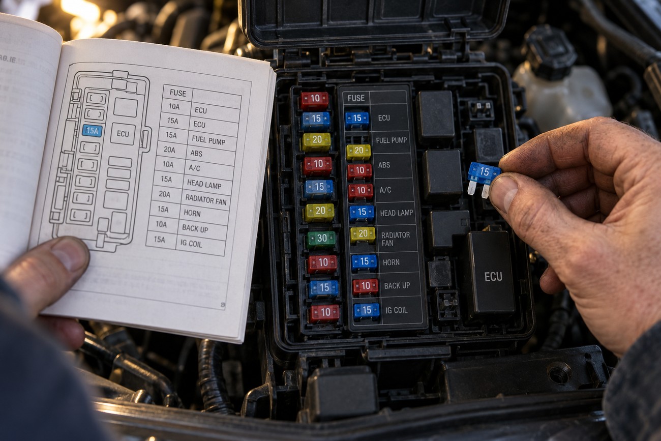
Start with the vehicle documentation and the fuse-box cover or label. Identify the circuit, fuse location, specified current rating, and any conditions required to energize it. A fuse can protect several devices, so the name on the diagram may describe a system rather than the component that first appears to have failed.
Check the fuse family and physical format as well as its current rating. Blade fuses, cartridge fuses, bolt-down fuses, and other designs are not interchangeable simply because they carry the same current. The replacement must match the original current rating, fuse type, and physical mounting format.
Color can help identify some automotive blade fuses, but it is not sufficient on its own. Read the printed value and compare the body shape, terminal arrangement, and seating method with the original or the vehicle specification. Installing a fuse in the wrong position can disable another circuit or create a dangerous mismatch.
Current rating is only one part of the specification. The replacement voltage rating must be at least the circuit’s maximum voltage, and its interrupting capacity must suit the available short-circuit current. For ordinary low-voltage automotive service, the vehicle manufacturer’s specified part is the safest reference because it accounts for the circuit and fuse-holder design.
How to Test an Installed Fuse With Voltage
A voltage test can check an installed fuse without removing it. Set a test light or voltmeter to a suitable DC voltage range, connect the reference lead to a reliable ground, and touch the probe to each accessible test point on the top of the fuse. The circuit must be properly energized, which may require the ignition, relay, switch, or load to be turned on according to the wiring diagram.
Voltage at both fuse test points indicates that the fuse is conducting. Voltage on one side only strongly indicates an open fuse, because power reaches the input side but cannot pass through the broken element. This method can reveal a failed fuse that looks normal from above.
No voltage on either side does not prove that the fuse is good or bad. The circuit may not currently be energized, a relay or control module may not have enabled it, or the fault may be upstream of the fuse. Check the circuit conditions before condemning the fuse.
Use a test light carefully around electronic circuits and exposed terminals. A voltmeter places little load on a circuit, so it can sometimes show voltage through a weak connection or an unintended path; a test light may reveal that the supply cannot support even a modest load. Neither tool replaces the wiring diagram when the readings do not fit the expected pattern.
How to Test a Removed Fuse With a Multimeter
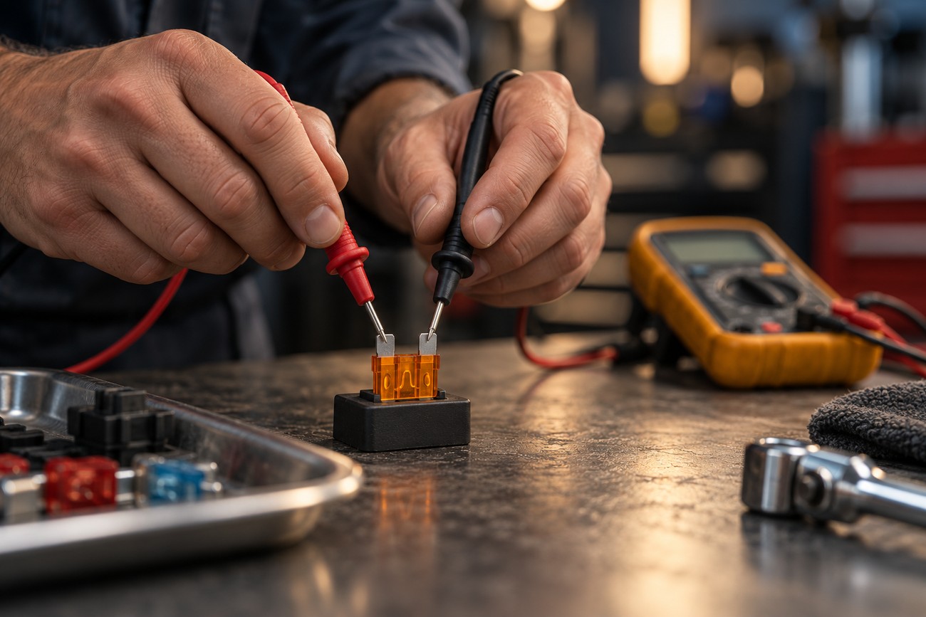
Switch off the ignition and electrical loads, remove the fuse, and confirm that the circuit is unpowered before testing resistance. Set the multimeter to continuity or resistance mode, then touch one probe to each fuse terminal. A healthy fuse normally has nearly zero resistance; approximately 0.5–1 ohm or less is a practical guide, depending on the meter and fuse type.
A blown fuse normally shows an open circuit or no continuity. Before judging a low reading, touch the two probes together and note the meter’s own resistance. The displayed value may not be exactly zero because the leads and probe contacts have resistance.
Do not measure a fuse while it remains connected to the vehicle unless you are using a method specifically intended for an energized circuit. Parallel paths through lamps, modules, relays, or other wiring can give a misleading resistance reading. Removing the fuse isolates the component and makes the result easier to interpret.
Visual inspection alone is not conclusive. The element may have a microcrack that is difficult to see, and the fuse itself may test correctly while its holder has corrosion, poor contact, loose tension, or a cracked connection. A continuity result confirms a low-resistance path at the time of testing; it does not prove that the fuse holder will carry operating current without heating.
Replace the Fuse Without Defeating the Protection
First verify the circuit and the specified fuse from the vehicle documentation. Switch off the ignition and loads as required, remove the old fuse with suitable tools, and compare its markings and format with the replacement. Inspect the socket for discoloration, corrosion, spread terminals, looseness, or signs of heat.
Install exactly the specified current rating, type, and physical format. The fuse should seat firmly without excessive force, rocking, or damage to the holder. After installation, switch on the relevant circuit and confirm that the equipment operates, while watching for heat, odor, noise, or another immediate failure.
Never install a higher-rated fuse to stop repeated failures. A larger current rating can allow the wiring to overheat before the fuse opens, creating a fire risk. Foil, wire, improvised links, and a fuse with a mismatched body style defeat the intended protection and can damage the vehicle.
A fuse may fail because of poor holder contact, corrosion, or a cracked connection even when the fuse element itself tests good. If the replacement does not restore power, test voltage at the fuse and at the device, then inspect the relay, connectors, ground, and wiring instead of repeatedly changing fuses.
If the New Fuse Blows Again, Stop Replacing It

Immediate or repeated fuse failure usually indicates a short circuit, overload, damaged wiring, or a faulty load rather than a defective replacement fuse. Stop installing replacements and identify what happens when the circuit is commanded on. Continuing to install fuses can turn a diagnostic problem into repeated component damage.
Begin with visible wiring, connectors, and the affected component. Look for insulation rubbed through against metal, crushed wiring, water intrusion, overheated terminals, loose grounds, and aftermarket equipment connected to the circuit. Follow the harness far enough to find movement points and areas exposed to heat or moisture.
A brief inrush current can blow a fuse even when the steady operating load appears normal. Motors, lamps, and other loads may draw more current during startup, while a failing motor or partially seized mechanism can make that event excessive. The correct response is to identify the load and verify the circuit design, not to increase the fuse rating.
Disconnecting the suspected load can help separate a faulty component from a supply-side short, but follow the wiring diagram and vehicle procedure. Some circuits contain multiple branches, relays, or control modules, so an unplugged device does not automatically prove that the device caused the failure.
The 80% guideline sometimes applies to continuous-load design contexts, but it is not a universal rule for replacing or increasing an automotive fuse. Fuse selection must remain tied to the specified circuit protection, wiring, load behavior, and manufacturer procedure.
When the Fuse Is Not the Real Problem
A good fuse does not rule out a failed relay, connector, ground, wire, or powered device. The fuse only shows that its own element can conduct; it does not prove that voltage reaches the load or that the load can operate. A circuit can therefore pass a fuse test and still leave the equipment dead.
Use voltage measurements to localize the fault. Compare the supply at the fuse with the supply at the device, and check the ground side where the circuit design permits. Voltage at the fuse but not at the device points toward a relay, connector, wire, or control issue; voltage at the device with no operation points toward the ground or the device itself.
Continuity testing has a narrow purpose. It can show a low-resistance path at the moment of testing, but it does not show whether contacts will carry working current, whether a connector will develop voltage drop, or whether a fuse holder will overheat under load. A circuit may look electrically complete with no load and fail as soon as current flows.
Inspect terminals for looseness, oxidation, pushed-back pins, and heat damage. A poor connection can create resistance and heat without immediately blowing the fuse, while a damaged ground can make a healthy supply appear ineffective. If the fuse and wiring checks pass, test the relay and the load using the manufacturer’s circuit information.
Frequently asked questions
What is the 80% rule for fuses?
The 80% concept is a design guideline used in some continuous-load contexts. It helps engineers account for sustained current and operating conditions, but it is not a universal rule for choosing a replacement automotive fuse.
It does not authorize fitting a larger fuse when the specified fuse keeps opening. The replacement must retain the specified current rating, type, and format unless an approved vehicle or component design change states otherwise.
Why does a fuse have a voltage rating if the circuit voltage is lower?
The voltage rating relates to the fuse’s ability to safely interrupt an arc after the element opens. A fuse with the correct current rating may still be unsuitable if its voltage rating is below the maximum voltage of the circuit.
The replacement voltage rating must be no lower than the circuit’s maximum voltage. Interrupting capacity also matters because the fuse must safely stop the available short-circuit current.
How can I test whether a fuse is blown?
Remove the fuse and test it across its two terminals with a multimeter set to continuity or resistance, after fully de-energizing the circuit. Nearly zero resistance, approximately 0.5–1 ohm or less depending on the meter and fuse type, indicates a conducting fuse; an open circuit indicates a blown fuse.
For an installed fuse, compare voltage at both test points while the circuit is correctly energized. Voltage on both sides indicates conduction, while voltage on one side only strongly indicates an open fuse. A continuity result alone does not prove reliable operation under load.
How do I test and replace a blown fuse with a multimeter?
Identify the correct fuse from the vehicle documentation, switch off the ignition and electrical loads, remove the fuse, and confirm the circuit is unpowered. Check the multimeter leads by touching them together, then measure across the fuse terminals. Replace an open fuse only with one matching the specified current rating, voltage rating, type, physical format, and suitable interrupting capacity.
After installation, operate the circuit and retest it. If the new fuse blows immediately or repeatedly, stop replacing it and inspect for a short circuit, overload, damaged wiring, poor connections, or a faulty load.