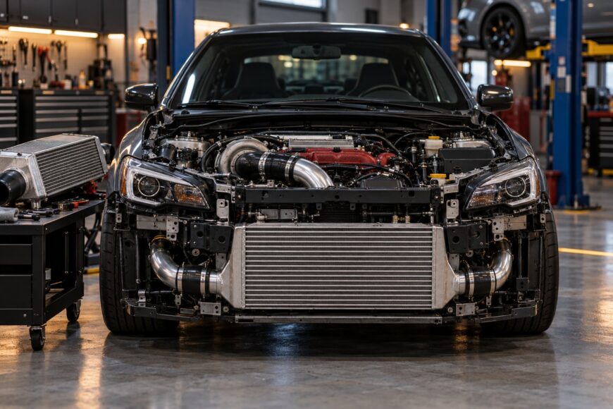
Turbocharged cars become less consistent as intake temperature rises. Hot compressed air is less dense, and the engine may respond with less ignition timing, reduced boost, or greater knock sensitivity. A front-mount intercooler (FMIC) can address that problem by placing the charge-air cooler in the vehicle’s main airflow path.
A larger FMIC is not automatically a faster upgrade. The result depends on charge-air temperature, pressure drop, turbocharger response, radiator airflow, pipe volume, installation quality, and how the car is driven. A system that performs well on a moving track may behave differently in slow traffic, while an impressive temperature reduction can be offset by leaks or excessive restriction.
The useful question is whether the complete intercooler system improves the engine’s operating conditions under matched tests. A credible evaluation considers temperature before and after the core, pressure at its inlet and outlet, ignition corrections, boost behavior, and repeatability rather than relying on a single intake-temperature reading or an advertised horsepower rating.
- What a Front-Mount Intercooler Actually Changes
- The Real Benefits: Cooler Air, Less Heat Soak, More Consistency
- Pressure Drop, Turbo Lag, and Heat-Soak Trade-Offs
- How to Choose the Right FMIC Size and Core Design
- Installation, Cooling-System Clearance, and ECU Calibration
- Front-Mount vs Top-Mount: Which Setup Fits Your Turbo Car?
- Frequently asked questions
- How much horsepower can a front-mount intercooler add?
- How can I tell whether an FMIC is too large for my car?
- What data should I log after installing a front-mount intercooler?
What a Front-Mount Intercooler Actually Changes
A turbocharger raises intake pressure by compressing air, and compression also raises its temperature. The intercooler removes some of that heat before the air reaches the throttle body and cylinders. A front-mount unit usually receives more direct ram air than a top-mount system, especially once the vehicle is moving at sustained speed.
Intake air temperature, often abbreviated as IAT, describes the temperature measured at a particular point in the intake system. The sensor location matters: temperature before the intercooler, after the intercooler, and near the intake manifold can differ substantially. A lower post-intercooler reading is useful evidence, although it does not by itself prove a power increase because boost control, ignition timing, fueling, and engine protection strategies also affect output.
Intercooler efficiency is the actual charge-air temperature drop divided by the maximum possible temperature drop relative to ambient conditions. It changes with mass airflow, vehicle speed, outside temperature, and the stability of airflow through the core. A test taken during a short pull at highway speed can therefore produce a different result from a repeated acceleration run in warm traffic.
Cooler air is denser at the same pressure. As an engineering approximation, each 10°C reduction in charge-air temperature corresponds to approximately 3–4% higher air density. That creates the potential for up to approximately 3% more power without changing boost pressure, although the engine must be able to use the additional oxygen and the ECU must maintain suitable timing and fueling.
The Real Benefits: Cooler Air, Less Heat Soak, More Consistency
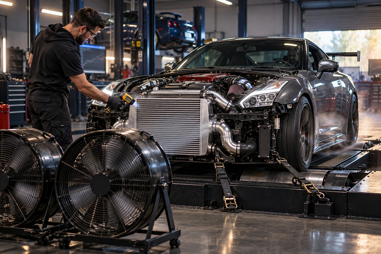
The clearest FMIC benefit is usually lower intake temperature during sustained airflow. Forum logs from Subaru and VAG applications commonly report approximately 10–30°C lower intake temperatures than a stock top-mount under comparable conditions. The range is application- and test-dependent, so ambient temperature, vehicle speed, engine load, sensor position, and the duration of the pull must match before the numbers can be compared.
Heat soak is often more important than the result of a single acceleration. A top-mount intercooler can absorb heat from the engine bay and lose effectiveness between repeated pulls. An FMIC generally has greater cooling potential while air is passing through the front of the car, which can help the engine deliver more consistent performance during back-to-back acceleration or sustained load.
The density calculation explains the potential rather than guaranteeing a dyno result. A 10°C reduction may correspond to approximately 3–4% higher air density, yet actual output depends on ECU calibration, ignition timing, fueling, turbocharger efficiency, and the engine’s knock or thermal limits. If the original system already allows the ECU to maintain full timing, a cooler intercooler may improve repeatability more than peak power.
Short street pulls can conceal the advantage. A car may feel nearly identical on the first acceleration, then retain more boost and timing on the third or fourth run after the factory intercooler has heat-soaked. Conversely, a large FMIC may show little benefit during a brief low-load drive if it has not received enough airflow to remove stored heat.
Pressure Drop, Turbo Lag, and Heat-Soak Trade-Offs
Every intercooler introduces some resistance to airflow. Pressure drop is the pressure difference between the core inlet and outlet at a defined mass airflow. A poorly matched large FMIC system may add approximately 1–3 psi of pressure drop compared with approximately 0.5–1 psi for many stock systems, while a well-designed kit is commonly expected to remain at approximately 1 psi or less under its intended operating conditions.
Pressure drop must be judged at the same mass airflow. A dashboard boost gauge cannot establish intercooler pressure drop because it normally shows pressure at only one point in the system. Practical engineering targets often fall around 0.5–2 psi at working airflow, and claims below 0.5 psi need the airflow, pressure locations, temperature, and test method to be credible.
Pipe volume also affects response. Large-diameter pipes, long routes, and multiple bends increase the volume that the turbocharger must pressurize. That can lengthen filling time or create the impression of greater turbo lag, even if the intercooler itself cools efficiently. Excessive restriction creates the opposite problem: air speed and pressure losses rise, which can limit high-power airflow.
Charge-pipe leaks should be ruled out before a larger intercooler is blamed for slow spool. A pressure test can reveal a loose coupler or poor seal that feels exactly like a weak turbocharger or excessive system volume.
Heat soak also remains possible with an FMIC. In stationary traffic or slow driving, the core may absorb heat from the nearby radiator, condenser, and engine bay because external airflow is limited. Recovery begins when vehicle speed and airflow increase, so the front-mount advantage is strongest during moving, sustained load rather than while idling in a queue.
One comparative test reported approximately 1.5 psi peak and 1 psi average pressure drop for an FMIC, versus approximately 1.5 psi peak and 0.9 psi average for the stock system. That example shows why a front-mount design cannot be judged by core size alone. A larger unit can cool well while producing a similar measured restriction to the factory system if the core, end tanks, and piping are properly matched.
How to Choose the Right FMIC Size and Core Design
Choose the core for the engine’s maximum expected mass airflow and intended use. An intercooler sized for ordinary street driving may become inefficient at the airflow demanded by a modified turbocharger, while an oversize unit adds weight, volume, packaging problems, and possible cooling-system blockage. The advertised horsepower rating is useful only when the manufacturer explains the airflow and test conditions behind it.
Efficiency can fall as mass airflow rises because the air spends less time transferring heat through the core. The design therefore needs enough frontal area and internal volume for the engine’s maximum operating demand, with acceptable pressure drop at that point. A core that performs well at moderate airflow may show a different balance at the engine’s top-end flow rate.
End-tank design deserves the same attention as the core. Poorly shaped tanks can feed one part of the matrix more heavily than another, creating uneven cooling and unnecessary pressure loss. Tube diameter, fin design, core thickness, and the route from the turbocharger to the throttle body all influence the result.
Manufacturers should ideally publish pressure at the intercooler inlet and outlet at the same mass airflow, along with intake temperatures and ambient conditions. Claims that omit airflow or test method cannot show whether a low pressure-drop figure applies to your engine. A credible comparison also considers pipe length, the number of bends, sensor placement, and whether the test used steady or changing airflow.
Installation, Cooling-System Clearance, and ECU Calibration
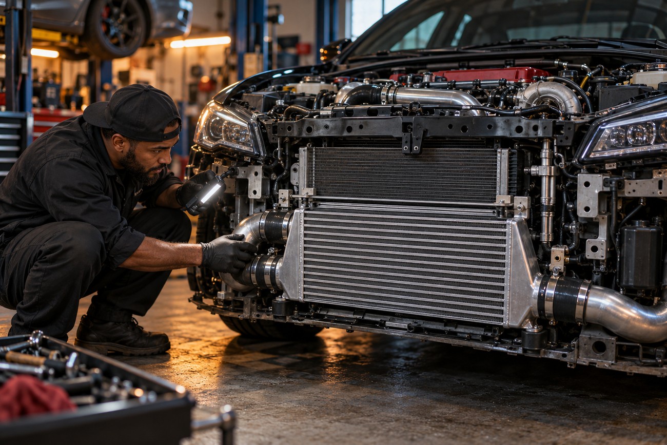
FMIC installation can require bumper trimming, relocated mounts, revised charge piping, new silicone couplers, and changes to sensor placement. Fitment problems often appear at the final connections, where a pipe touches the chassis, a coupler sits at an angle, or a bracket transfers vibration into the core. These details affect durability as well as airflow.
Front-end space is shared with the radiator and air-conditioning condenser. Blocking a significant portion of their airflow can raise engine coolant or air-conditioning temperatures, particularly during hot weather and low-speed operation. The largest available core may therefore be unsuitable if its frontal area leaves insufficient clean airflow for the rest of the cooling stack.
Every connection should be pressure-tested after installation. A leak can produce slow spool, unstable boost, poor fuel trims, or a weak-feeling engine, and it is easy to misdiagnose those symptoms as a turbocharger problem. Clamps, bead rolls, couplers, and sensor fittings deserve inspection after the first heat cycles because movement and temperature changes can expose marginal seals.
Changing the intercooler system can alter intake temperatures and pressure behavior enough to justify ECU checking or returning. The final validation should include temperature before and after the intercooler, inlet and outlet pressure, boost behavior, ignition corrections, and measured power where available. The useful result is a repeatable improvement under matched conditions rather than a boost-gauge reading taken in isolation.
Front-Mount vs Top-Mount: Which Setup Fits Your Turbo Car?
Both layouts can work well when matched to the engine and the vehicle’s use. The table highlights the practical compromises that usually matter more than the intercooler’s advertised size.
| Factor | Front-mount intercooler | Top-mount intercooler |
|---|---|---|
| Airflow at speed | Usually benefits from direct front airflow and sustained ram air. | Uses a more limited hood or scoop airflow path. |
| Traffic behavior | Can heat-soak near the radiator and condenser when airflow is low. | Can absorb substantial under-hood heat, especially after repeated low-speed use. |
| Repeated pulls | Often provides stronger consistency once the car is moving. | May lose effectiveness sooner as heat accumulates. |
| Piping and response | Requires longer external piping; poor routing can increase filling time. | Usually keeps the charge path compact and response predictable. |
| Pressure-drop risk | Depends heavily on core, end tanks, pipe diameter, and routing. | Often has a shorter path, although the stock design still needs measurement. |
| Radiator clearance | Can reduce airflow to the radiator or condenser if poorly packaged. | Leaves the front cooling stack less obstructed. |
| Crash exposure | Core and pipes are more exposed to front-end impact damage. | Components are generally better protected inside the engine bay. |
| Typical use case | Sustained load, repeated acceleration, and higher airflow demand. | Compact street installations where response, space, and cooling-stack clearance matter. |
FMIC systems generally have better cooling potential under sustained airflow because they use the front of the vehicle. They also add external piping and front-end components, increasing installation complexity and potential impact exposure. A top-mount system can preserve compact response and radiator clearance, although it may be more vulnerable to under-hood heat and limited airflow.
Climate and driving pattern should influence the decision. A car used for repeated highway pulls or track sessions may gain more from the FMIC’s airflow advantage, while a car that spends most of its time in slow traffic may require careful ducting and cooling-stack evaluation. The same core can produce different results in a cool, fast environment and a hot urban commute.
The best setup balances charge-air temperature, pressure drop, response, cooling-system airflow, and packaging. A compact top-mount can be the better engineering choice for a moderate street build, while a properly designed FMIC becomes more compelling as sustained airflow demand and heat load increase.
Frequently asked questions
An FMIC upgrade should be judged by measured operating conditions rather than by a universal power claim. These answers focus on the checks that separate a useful installation from a large intercooler that merely looks impressive.
How much horsepower can a front-mount intercooler add?
There is no fixed horsepower gain for an FMIC. A temperature reduction can increase charge-air density, and the stated approximation gives approximately 3–4% higher density for each 10°C reduction, with up to approximately 3% potential power increase without changing boost pressure. That is a potential effect, not a guaranteed dyno result.
A genuine improvement should be separated from restored ignition timing or better repeatability after heat soak. Compare matched runs with the same fuel, boost target, ambient conditions, and engine temperature, then review intake temperature, ignition corrections, and measured power together. A single higher dyno number can reflect changing intake temperatures or correction factors rather than the intercooler alone.
How can I tell whether an FMIC is too large for my car?
Warning signs include noticeably slower spool, excessive pressure drop at the engine’s working airflow, difficult pipe routing, poor bumper or bracket fitment, and blocked radiator or condenser airflow. A large core is also a poor match if intake temperature does not recover during the car’s actual driving pattern despite adequate vehicle speed.
Check for leaks before judging response, then compare inlet and outlet pressure at the same mass airflow. If the system causes cooling problems, requires extreme pipe volume, or delivers no repeatable temperature advantage under normal use, a smaller and better-matched design may be more effective.
What data should I log after installing a front-mount intercooler?
Log intake temperature before and after the intercooler where possible, pressure at the intercooler inlet and outlet, boost, engine speed, load, and ignition corrections. Record ambient temperature, vehicle speed, gear, and the duration of each pull so the runs can be compared under similar conditions.
Use matched single pulls and repeated acceleration runs. Look for lower post-intercooler temperature, acceptable pressure drop, stable boost, preserved ignition timing, and improved repeatability as heat builds. If available, measured power should support those trends rather than stand alone as proof.