
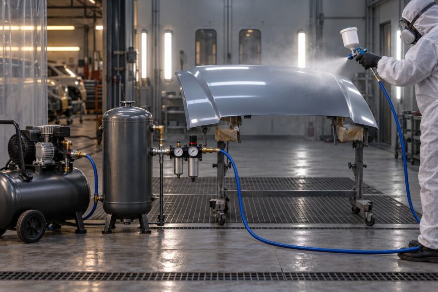
A compressor can show adequate pressure while the spray pattern collapses, water reaches the workpiece, or coverage becomes uneven. The receiver gauge may look healthy because it measures stored air, while the gun is being starved through a restrictive hose, fitting, filter, or regulator.
Reliable spray painting starts with matching the spray gun’s actual air demand and pressure under load. Tank size and headline PSI provide useful context, but they do not prove compatibility. Short touch-up work may draw on stored air briefly; continuous panel spraying depends on the compressor’s delivered airflow.
The correct setup also needs clean, dry, regulated air. Pressure must be checked at the gun with the trigger fully pulled, and moisture control must account for condensation farther down the line.
- What a Spray Gun Actually Needs From an Air Compressor
- How Much CFM Does a Spray-Painting Compressor Need?
- The Specifications to Compare Before You Buy
- Measure Pressure at the Gun, Not Just at the Tank
- Prevent Water and Contamination in the Spray Line
- Why Spray Patterns Collapse: Common Setup Errors and Hidden Restrictions
- A Practical Compressor-Sizing and Setup Checklist
- Frequently asked questions
- What is the minimum air compressor size needed for spray painting?
- How can I tell whether a quick-connect or hose is restricting my spray gun?
- Why can the compressor gauge look normal while the spray gun loses pressure?
- How should I interpret a compressor rating listed at 90 PSI?
What a Spray Gun Actually Needs From an Air Compressor
A spray gun needs four things from its compressor system: enough airflow, the correct operating pressure, stable delivery, and clean, dry air. Air consumption must be matched to the specific gun manual at the same operating pressure. A compressor that reaches the required PSI with no load may still fail to supply the volume needed during a long spray pass.
Pressure readings also need careful interpretation. Pressure at the gun inlet is the regulated supply entering the tool. Pressure at the air cap is a separate measurement that describes the atomizing air at the cap. For HVLP equipment, air-cap pressure is limited to 10 PSI (0.7 bar), while inlet pressure may be approximately 14–28 PSI, depending on the spray gun and setup.
These figures cannot be substituted for one another. Setting the inlet pressure by confusing it with air-cap pressure can produce poor atomization, excessive overspray, or an operating condition outside the manufacturer’s instructions. Exceeding the specified pressure may also create a safety issue.
Air quality affects the finish as much as pressure does. Oil, water, and debris can cause defects, contaminate the coating, and make the fan unstable. The spray air must therefore be clean, dry, and regulated at the point where it enters the gun.
How Much CFM Does a Spray-Painting Compressor Need?
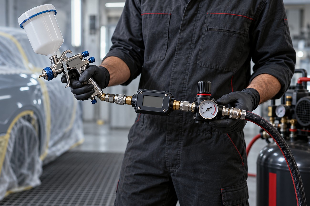
There is no universal minimum compressor size for spray painting. Air demand changes with spray-gun design, nozzle, operating pressure, coating, and working technique. The gun manual is the primary source because its stated CFM requirement describes the actual tool you intend to use.
Some HVLP models specify approximately 12–13 CFM at 26–45 PSI. Approximately 12 CFM is also sometimes recommended for continuous HVLP operation, but this is a rule of thumb rather than a universal requirement. Individual spray guns may require substantially less or more, so a generic “HVLP compressor size” can mislead you.
Short localized work has a different demand from continuous panel spraying. A receiver tank can temporarily supply stored air and smooth a brief shortfall while you spray a small area. Once the stored air is depleted, the compressor’s actual output determines whether pressure remains stable.
During a long pass, an undersized system may show a narrowing fan, weaker atomization, and uneven coverage. Increasing pressure can hide the problem briefly, yet it does not replace missing airflow and may move the gun outside its specified operating regime.
The Specifications to Compare Before You Buy
Compare the spray gun’s air demand with the compressor’s actual delivered output at comparable pressure conditions. Treat tank volume and headline PSI as supporting specifications rather than proof that the system will spray continuously.
| Specification | What to compare | Why it matters |
|---|---|---|
| Spray-gun air consumption | CFM stated in the gun manual at its operating pressure | Defines the airflow the tool needs under its intended setup. |
| Compressor output | Delivered CFM measured at a comparable pressure | Shows whether the compressor can supply the gun under load. Advertised input or headline figures may differ from actual delivered output. |
| Measurement pressure | The pressure used for both the gun and compressor figures | A compressor rating at one pressure cannot be directly compared with gun consumption at another. |
| Tank volume | Receiver capacity viewed as stored-air support | A large tank can smooth short work, but it does not turn a low-output compressor into a continuous air source. |
| Pressure rating | Gun inlet requirement and compressor operating range | Pressure must remain within the gun manufacturer’s specification; PSI alone does not establish airflow compatibility. |
Measure Pressure at the Gun, Not Just at the Tank
Pressure can fall between the receiver and the spray gun. Filters, regulators, hoses, quick-connects, and fittings all introduce resistance, and the loss becomes more visible when the gun is consuming air continuously.
Set and check pressure with the spray-gun trigger fully pulled at the gun inlet. A static reading with the trigger released only shows pressure in a no-flow condition. The loaded reading shows what the gun actually receives while spraying.
The tank gauge may remain normal while the spray pattern fails because the receiver contains stored air, while the downstream path cannot deliver enough volume. A narrowing fan or unstable atomization during a long pass points toward delivery loss, insufficient compressor output, or both.
Do not compensate by raising pressure without checking the manual. Higher pressure does not replace insufficient airflow, and it can disrupt the HVLP operating regime. Tank pressure, gun-inlet pressure, and air-cap pressure are separate measurements with different purposes.
Prevent Water and Contamination in the Spray Line
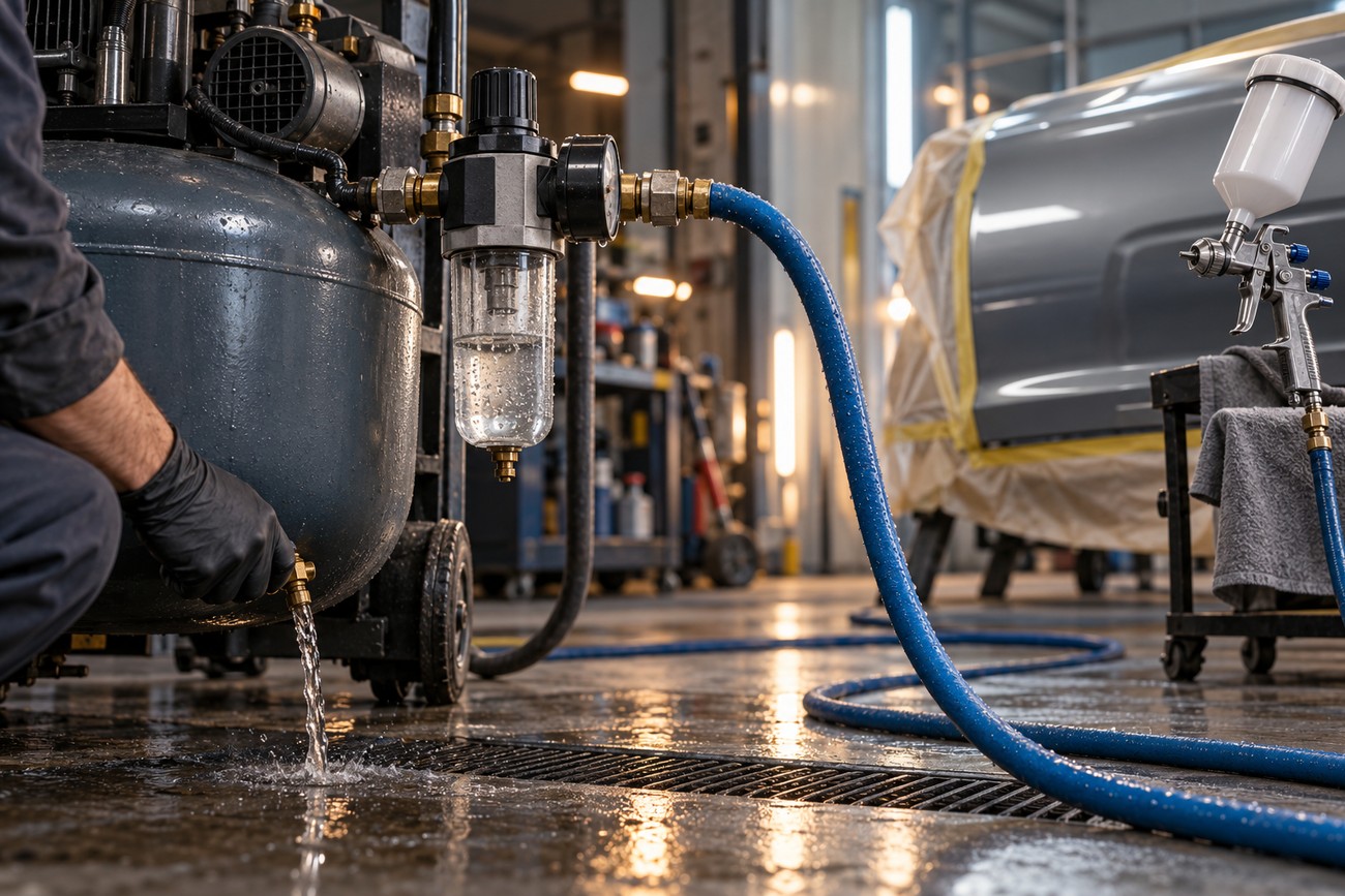
Water can reach the workpiece even when the compressor is functioning correctly and has a factory moisture separator. Compressed air heats during compression, then cools in the hose and fittings. That temperature change can cause moisture to condense farther down the line.
Humidity makes the problem more persistent, especially in hot, humid conditions. A separator near the compressor may remove moisture already collected there, while condensation forms later in a cool hose. Drain the receiver, purge the line, and inspect the system before adding paint.
Air that leaves the compressor dry can still deliver water after the line cools. A second moisture separator close to the spray gun is useful in humid conditions because it protects the final section of hose and the tool inlet.
For a simple air-quality check, direct purged air onto a clean, thin cloth before connecting the paint supply. Wet marks or spots indicate moisture transfer. In high humidity, two separation points may be useful: one near the compressor and another closer to the gun.
Why Spray Patterns Collapse: Common Setup Errors and Hidden Restrictions
A pressure sag during a long pass usually means the system cannot maintain delivered airflow under load. The receiver may still show normal pressure, while the compressor output, hose, or fittings fail to keep pace with the gun. The practical symptom is a fan that narrows as the pass continues.
Long or narrow hoses increase resistance, and restrictive quick-connects can reduce flow even when the hose itself appears adequate. Check the entire delivery path rather than replacing the compressor immediately. Compare the loaded pressure and spray behavior with a shorter or less restrictive path, changing one component at a time.
Uneven coverage can also result from comparing mismatched specifications. A compressor CFM rating measured at one pressure cannot be directly compared with spray-gun consumption measured at another. Find delivered-output data under comparable conditions, then verify the result at the gun inlet.
Water spots have a different immediate cause, although they can appear alongside airflow problems. Drain the receiver, purge the hose, test the air on a clean cloth, and inspect the separator near the gun. A factory filter does not guarantee that condensation will be removed after the air travels through the line.
Pressure adjustment is another common error. Setting the regulator by the tank gauge or raising pressure to force a weak fan can produce misleading results. Measure with the trigger fully pulled, confirm the gun’s inlet requirement, and treat stable airflow as a capacity issue rather than a pressure-setting issue.
A Practical Compressor-Sizing and Setup Checklist

Start with the exact spray-gun model and nozzle. Record the manual’s CFM requirement and inlet-pressure range, then identify whether the compressor specification describes delivered output under comparable pressure conditions. If the compressor only lists a headline or input figure, treat compatibility as unconfirmed until better performance data is available.
- Match the gun’s air consumption to the compressor’s actual delivered output at a comparable pressure.
- Account for losses through the regulator, filters, hose, quick-connects, and fittings.
- Install moisture control, drain the receiver, and purge the line before spraying.
- Check pressure with the trigger fully pulled at the gun inlet.
- Test purged air on a clean, thin cloth before adding paint.
- Run a spray test and watch for pressure sag, a narrowing fan, or uneven coverage during a long pass.
For short touch-up jobs, receiver capacity may temporarily support a compressor that falls short of continuous demand. That does not make the setup suitable for large panels or sustained spraying. The compressor must recover quickly enough to maintain the gun’s required airflow.
For continuous panel work, choose sufficient ongoing output based on the gun manual and allow practical margin for line losses. There is no universal CFM or tank-size answer. Verify both pressure and air cleanliness at the gun, rather than inferring performance from the compressor gauge.
Frequently asked questions
The questions below address common compressor-sizing and spray-line problems. They focus on airflow, pressure measurement, and restrictions between the compressor and gun. Use the spray-gun manual and loaded readings at the gun as the primary references.
What is the minimum air compressor size needed for spray painting?
The minimum depends on the exact spray gun, nozzle, pressure, and duty cycle. Short localized work may temporarily use receiver capacity, while continuous spraying requires the compressor’s delivered output to meet the gun’s stated airflow demand under comparable pressure.
Use the gun manual as the deciding reference. Some HVLP models specify approximately 12–13 CFM at 26–45 PSI, while other guns require substantially less or more. Tank volume and PSI alone cannot establish compatibility.
How can I tell whether a quick-connect or hose is restricting my spray gun?
Check pressure at the gun inlet with the trigger fully pulled, then observe the fan during a sustained spray pass. If pressure or spray behavior improves with a shorter hose or different connector, the removed component was contributing to the restriction.
Change one hose or fitting at a time and repeat the loaded test. This isolates the delivery path more reliably than comparing static tank-gauge readings.
Why can the compressor gauge look normal while the spray gun loses pressure?
The compressor gauge usually shows stored receiver pressure, while the gun needs flowing air through the downstream system. Filters, regulators, hoses, quick-connects, and fittings can restrict delivery, so the tank remains pressurized while the gun inlet pressure falls under load.
Measure at the gun with the trigger fully pulled. That reading distinguishes stored pressure from loaded downstream pressure and helps separate a compressor-output problem from a restriction in the air line.
How should I interpret a compressor rating listed at 90 PSI?
A rating at 90 PSI describes performance under that measurement condition. It cannot automatically be treated as the compressor’s delivered output at the spray gun’s operating pressure.
Find compressor output data measured at a pressure comparable to the gun’s stated consumption, then allow for losses in the delivery path. Confirm the result with a loaded pressure check at the gun inlet.