A spray gun can produce a narrow strip, dry edges, a heavy center, or workshop-wide mist even when the fan screw is turned in the expected direction. The visible pattern results from several controls working together, so a correct-looking fan adjustment may still produce a poor coating.
Fan width is only one part of the system. Air pressure, fluid flow, nozzle size, coating viscosity, gun distance, and hand speed all affect the result. Reliable adjustment starts with a controlled baseline and a test panel, then changes one variable at a time instead of chasing defects with the fan control alone.
- What the Fan Adjustment Actually Controls
- Set a Reliable Baseline Before Adjusting the Fan
- How to Adjust the Fan Pattern Step by Step
- Read the Test Pattern and Correct the Real Cause
- Match the Fan to the Nozzle, Coating, and Part
- Common Mistakes, Hidden Failures, and Maintenance Checks
- Frequently asked questions
- Why is my spray fan tilted or curved even when the settings seem correct?
- How often should I clean the air cap when adjusting the fan?
- What is fan adjustment on a spray gun?
- What are the adjustments on an HVLP spray gun?
- How do you adjust PSI on a sprayer?
What the Fan Adjustment Actually Controls
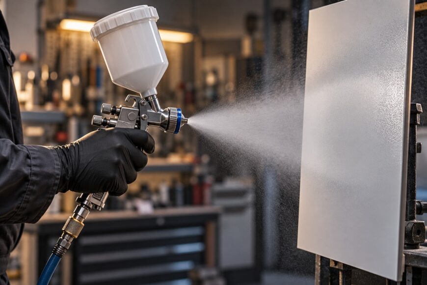
The fan-pattern control changes the spray shape from round toward an oval or flat pattern. With the fan more closed, the gun produces a narrower stream that can suit small areas or detailed work. Opening the control spreads the atomized material across a wider path.
This control does not directly increase paint output. Fluid volume is governed by the material adjustment, nozzle, trigger movement, and coating properties, while atomization is also affected by air pressure. Opening the fan while leaving excessive fluid flow unchanged can make a wide pattern look attractive in the air and flood the workpiece in practice.
The useful target is an even, controllable pattern with similar density from one end to the other. A wide fan is not automatically better: it can increase overspray, edge losses, and material consumption, especially on narrow parts. The best practical fan is the widest pattern that remains evenly dense and manageable for the particular surface.
Every gun has its own relationship between the fan control, air cap, nozzle, and fluid needle. Manufacturer settings are therefore a starting point rather than a universal recipe. If the pattern changes sharply when you move from primer to clear coat, that usually indicates a changed material system, not a fault in the fan adjustment itself.
Set a Reliable Baseline Before Adjusting the Fan
Begin with the spray gun manual, a clean air supply, and coating prepared according to its instructions. Strain the material, confirm its viscosity using the specified method, and fit a nozzle suitable for that coating. A nozzle that is too small can make a material difficult to atomize; a nozzle that is too large can deliver more fluid than the air and movement can control.
Pressure figures are reference points, not universal targets. Accessible technical references commonly give about 1.5–2 bar inlet pressure for many HVLP systems and about 0.7 bar at the air cap. Conventional spray guns more often use about 3–4 bar, but the exact requirement depends on the gun and coating system.
Check pressure with the trigger fully pulled, because the reading can fall while air is flowing. An idle gauge reading may look correct while the gun receives too little air during spraying. HVLP and LVLP guns commonly require about 150–350 L/min, and some HVLP models are specified up to 30 m³/h, so the compressor, hose, regulator, and fittings must maintain the required flow.
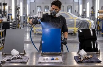
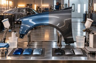
Test on cardboard or a prepared panel before approaching the workpiece. Keep the gun square to the panel, use a consistent distance and hand speed, and make the first test with a conservative fan opening. Record what you change. If pressure, fluid flow, and fan width are all altered together, the test may improve without showing which adjustment solved the problem.
How to Adjust the Fan Pattern Step by Step
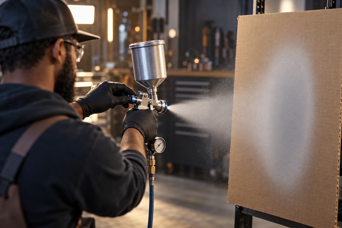
Start from the manufacturer’s baseline with the fan partly closed or at the specified initial position. Make a short pass on the test panel while holding the gun at a consistent distance and moving at a steady speed. The first objective is to see the distribution of material, not to create the widest possible stripe.
Open the fan gradually and repeat the test after each small change. Watch the full pattern, including both ends, and compare its density with the center. If the edges become light while the middle becomes heavy, balance fluid flow, pressure, and viscosity before opening the fan further.
Adjust only one control at a time. If the fan width is acceptable but the coat is too wet, reduce fluid flow or review viscosity rather than immediately increasing air pressure. If atomization is coarse, check the specified pressure and material preparation first; a wider fan cannot correct an unsuitable coating setup.
A correctly adjusted pattern has consistent density across its length, without excessive edge buildup or a flooded center. It should transfer material predictably during a pass, with enough overlap for the job and no large cloud of material missing the part. On a small component, a narrower but more controllable fan may produce a better finish than the maximum opening.
Keep the air cap square to the surface and maintain a consistent overlap as you work. Tilting the gun changes the distance and angle across the fan, which can make one side appear dry even though the fan is mechanically correct. Hand speed matters as well: moving slowly loads the surface, while moving too quickly can leave dry spray and rough texture.
Read the Test Pattern and Correct the Real Cause
A heavy center usually means the relationship between fan opening, fluid flow, pressure, and viscosity is wrong. First confirm that the coating is prepared correctly and that the nozzle is appropriate. Then check fluid flow and fan width before making a small pressure adjustment. Simply adding air may create a finer cloud while leaving the center distribution unresolved.
Dry edges or tails can result from excessive fan opening, insufficient material, low pressure, excessive gun distance, or material that is too viscous. They can also appear when the gun is not held square to the panel. Reduce the fan temporarily and compare the test pattern; if the narrower pattern becomes even, the original setting was beyond the useful range for that material and distance.
Judge density and edge behavior on the test panel before widening the fan. A visually impressive spray cloud can hide poor transfer and unnecessary material loss.
Spitting, droplets, or interrupted streams point toward a different group of checks. Inspect the material supply, fluid passages, nozzle seating, and trigger operation, then verify that pressure does not collapse when the trigger is pulled. Too little pressure can produce droplets, interrupted streams, orange peel, and rough texture.
Too much pressure can create fine mist, dry spray, and material loss. If the workshop fills with overspray and the coating lands dry, reduce pressure toward the specified range and check whether the material is too thin or the gun is too far from the surface. Orange peel can also result from insufficient air, excessive viscosity, or movement that is too fast.
Fan adjustment cannot compensate for coating that is too viscous, poorly strained, or inadequately mixed. If the same gun works on one material and spits on another, reset the material preparation and nozzle selection before assuming the fan mechanism is defective. The test panel separates a true pattern problem from a coating problem.
Match the Fan to the Nozzle, Coating, and Part
The fan setting must match the coating’s flow behavior and the nozzle’s capacity. Practical reference bands place thin materials around 0.6–1.3 mm, acrylic paints and clear coats around 1.4–1.6 mm, primers around 1.6–2.2 mm, and liquid filler around 2.5–3.0 mm. These are working ranges, not a substitute for the coating and gun manufacturer’s specifications.
A larger nozzle can support heavier material, but it also changes fluid delivery and the amount of air needed for useful atomization. A small nozzle with thick coating may encourage you to raise pressure until the gun produces a mist, while a large nozzle with thin coating may flood the center. In both cases, the fan screw is being asked to solve a nozzle and material mismatch.
Narrow parts, edges, and small repairs require control at the boundaries, so a moderate fan may be more economical than a broad one. Large panels can benefit from a wider fan if the compressor maintains stable air and the operator can keep distance, angle, and overlap consistent. The correct choice is determined by the part and control requirements, not by width alone.
Transfer-efficiency figures also need careful interpretation. Conventional systems are often cited at about 40–50% transfer efficiency, while AirMix systems may reach up to 86%. A higher figure can reduce material losses under suitable conditions, but it does not replace surface preparation, correct viscosity, a suitable nozzle, or consistent spray technique.
Common Mistakes, Hidden Failures, and Maintenance Checks
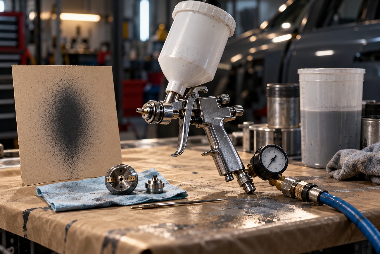
One common mistake is testing the fan in open air or judging it by sound. The pattern must be sprayed onto cardboard or a test panel, where density and edge behavior are visible. Setting pressure by eye is equally unreliable; use the recommended gauge position and check the reading with the trigger fully pulled.
Leaving fluid flow fully open makes fan diagnosis difficult. Excess material can create a heavy center even when the fan is correct, while too little material can make the edges appear dry. A single nozzle for every coating causes the same confusion because viscosity and solids content change the amount of air and fluid the gun needs.
Compressor capacity is a less obvious failure point. If the compressor cannot maintain the gun’s required air demand, the pattern may start correctly and then tear or become unstable as pressure drops. Long, narrow hoses, restrictive fittings, or a small regulator can produce a similar symptom even when the compressor specification appears adequate.
A fan that pulls to one side may have contaminated nozzle passages, blocked air-cap holes, or a worn or damaged air cap. Clean the gun according to its instructions and inspect the cap for dried coating or impact damage. If the pattern remains asymmetric after cleaning and correct assembly, replacing a damaged component may be more productive than changing pressure repeatedly.
The common myths are easy to summarize. A wider fan does not automatically provide better coverage, higher pressure does not automatically improve atomization, and one fan setting cannot suit every coating, nozzle, and viscosity. Pneumatic spraying is described in ISO terminology as applying coating material by air spraying; standards help define the process and its terms, but they do not provide universal fan settings for every gun.
Frequently asked questions
The answers below focus on faults and operating details that are easy to miss during a routine fan adjustment.
Why is my spray fan tilted or curved even when the settings seem correct?
A tilted or curved fan is often a mechanical or cleanliness problem rather than a pressure problem. Check the air-cap holes for partial blockage, confirm that the cap and nozzle are seated and aligned correctly, and inspect the cap components for damage. Uneven air from one blocked passage can push the pattern to one side even when the gauge and material settings are correct.
Clean with the tools and solvent approved for the gun. Avoid forcing unsuitable hard tools through small air-cap holes, because enlarging or damaging them can permanently change the pattern. If cleaning and correct assembly do not restore symmetry, the air cap or another worn component may need replacement.
How often should I clean the air cap when adjusting the fan?
Clean the air cap whenever the pattern changes, becomes asymmetric, or develops a new heavy edge. The decision should be based on the spray result rather than a fixed calendar interval, because coating type, working pauses, and cleaning discipline affect how quickly residue builds up.
During a longer job, inspect the cap if the fan becomes narrower, tilted, or less even after a material change. Soak or wipe it only as the manufacturer permits, and do not scrape the holes with unsuitable hard objects. A small deposit can disturb the air pattern enough to imitate an incorrect fan setting.
What is fan adjustment on a spray gun?
Fan adjustment is the control that changes the spray shape from round toward an oval or flat pattern. It changes distribution across the surface, while the fluid control primarily affects material flow. The useful setting is the widest pattern that remains evenly dense, controllable, and economical for the specific part.
What are the adjustments on an HVLP spray gun?
An HVLP gun generally allows you to set fan shape, fluid flow, and air pressure, although the control layout differs by model. Some systems also use a regulator at the gun or handle. Set these controls from the manual, then evaluate the result on a test panel because nozzle size, coating viscosity, and compressor capacity change the practical settings.
How do you adjust PSI on a sprayer?
Connect the regulator and set pressure according to the gun manufacturer’s specification, then pull the trigger fully while reading the gauge. Adjusting pressure with the gun idle can leave the spraying pressure too low because air demand causes a drop. Make small changes and check the test pattern after each one; do not raise PSI automatically to correct a material or nozzle problem.