

A metallic tick that persists after warm-up can prompt a valve-clearance check. So can an engine that sounds quiet but starts poorly when cold. Neither symptom proves that clearance is the cause; the useful first step is to measure each valve against the specification for that engine.
Valve clearance is a small, deliberate gap in a mechanically adjustable valvetrain. It allows the parts to expand as the engine heats up while still letting the valves close as intended. Because the required gap depends on the engine, adjustment should follow a measured result, not a guess based on noise or feel.
- What valve clearance does—and what symptoms cannot prove
- Find the right specification before reaching for a feeler gauge
- Prepare the engine and identify the valve you can measure
- How to measure and adjust valve clearance step by step
- When to check again—and when adjustment is not the repair
- Mistakes that make a careful adjustment unreliable
- Frequently asked questions
- What is the rule of nine for valve adjustment?
- What should I record when checking valve clearance?
- How do you adjust valve clearance step by step?
- What is the rule of 9 valve adjustment?
- What is the correct valve clearance?
What valve clearance does—and what symptoms cannot prove
Clearance provides room for thermal expansion between the parts that operate a valve. If the gap is too small, a valve may fail to close fully when the engine is hot. That can affect sealing and running even when the valvetrain makes little noise.
Excessive clearance can produce metallic ticking as the moving parts take up the extra gap. The sound may be most noticeable near the cylinder head, but other mechanical faults can make similar noises. A persistent tick is a reason to inspect, not a clearance measurement.
Hard cold starts, uneven running, or a change in response can also justify investigation. These symptoms have other possible causes, so setting the valves without checking them may leave the actual fault untouched. In particular, a quiet engine can still have insufficient clearance.
Find the right specification before reaching for a feeler gauge
Use service documentation for the exact engine to find the intake and exhaust clearances, the required measurement temperature, and the inspection interval. Check whether the specification gives a target value or an acceptable range. Similar-looking engines can have different requirements, so identification matters more than a general chart.
Published examples include intake clearances of 0.15–0.25 mm and exhaust clearances of 0.2–0.4 mm. Those ranges illustrate how specifications can differ; neither is a setting for an unidentified engine. Applying one of them without confirmation could turn an acceptable valve into an out-of-specification one.
First establish what type of valvetrain the engine has. Engines with hydraulic lash adjusters generally do not use the same routine mechanical adjustment procedure as screw-adjusted or shim-adjusted systems. If the documentation specifies an inspection interval, that means check and record the clearance; adjust only where the measured value requires it.
Prepare the engine and identify the valve you can measure

Follow the specified temperature condition before removing covers or taking readings. Many procedures call for a cold engine, but “cold” must be interpreted according to that engine’s instructions. Measuring after a short shutdown when the head is still warm can make a careful gauge reading irrelevant to a cold-engine specification.
Make enough room to reach the specified gauge contact point without bending the blade. Depending on the valvetrain, that point may be at a rocker, cam, or tappet interface. Have suitable feeler-gauge blades ready, and keep dirt away from the exposed components.
Rotate the engine by hand as directed in its service procedure. The valve being measured must be fully closed, with its cam lobe on the base circle rather than lifting the valve. Use compression-stroke top dead center as a positioning reference only where the manual calls for it; one rotation sequence does not suit every layout.
A valve held even partly open will give a misleading reading. Before trusting a surprising result, confirm both the valve identity and the cam position. That simple check can prevent an adjustment made to compensate for a positioning mistake.
How to measure and adjust valve clearance step by step
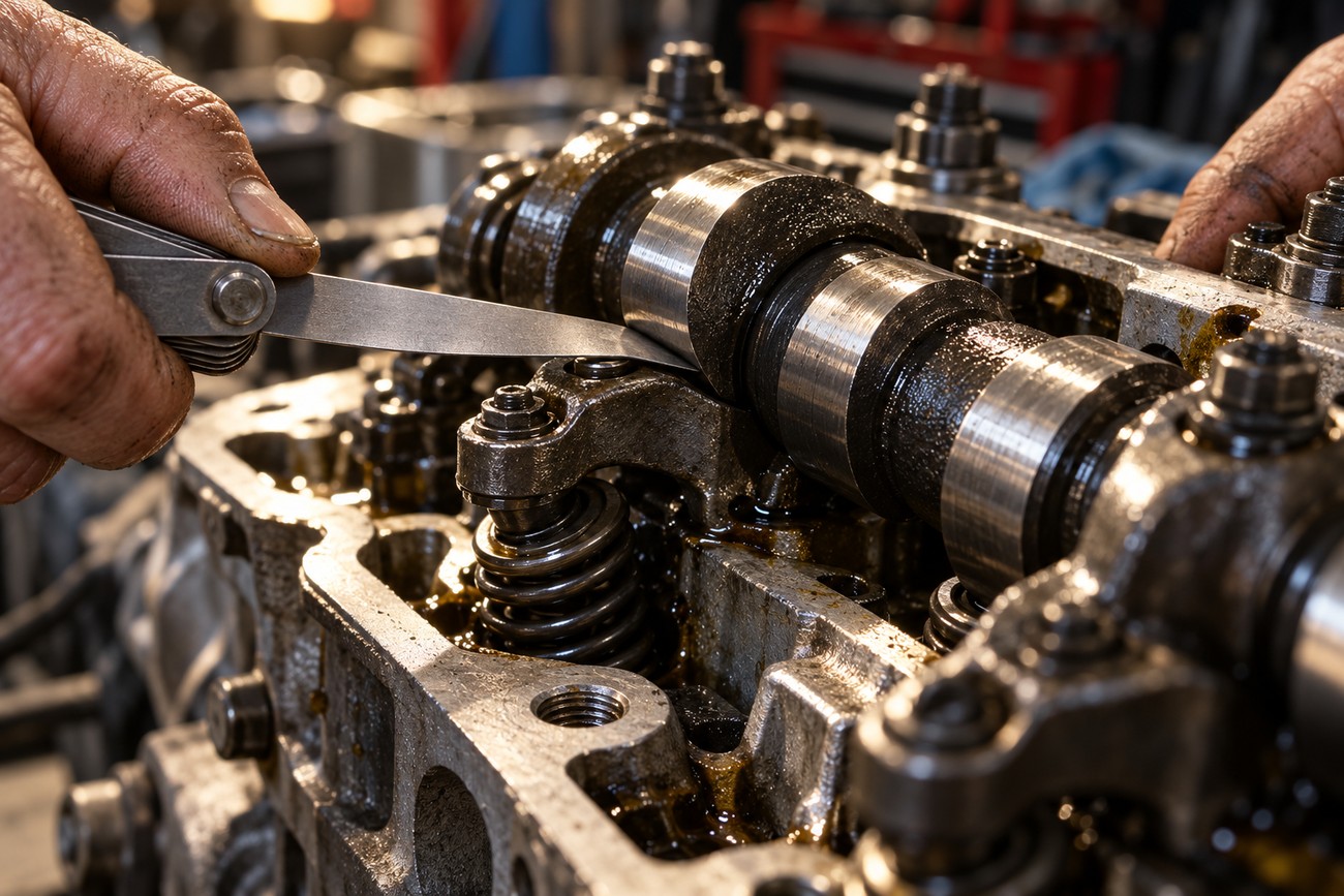
Position the first valve according to the engine’s procedure and identify it as intake or exhaust. Insert the specified feeler-gauge blade at the defined contact point, keeping it aligned with the gap. It should move with light, consistent drag; a blade that binds or slides freely does not give the same indication.
Record the reading and compare it with the applicable limit for that valve. Work through the valves in the order given for the engine, rather than assuming a universal firing-order method. If a reading is within specification, leave that setting alone unless the service instructions say otherwise.
Tightening a screw-adjuster lockout can shift the setting slightly. Judge the final clearance with a fresh gauge check after the lockout is secured, rather than relying on how the blade felt before tightening.
For a screw-and-lockout system, follow the specified procedure to set and secure the adjuster. A shim-based system instead requires the correct shim selection and, on some engines, further disassembly. Use the engine manual for those operations and for all tightening instructions; an estimated torque or improvised shim choice can create another fault.
Remeasure every valve you adjust after its setting is secured. Then check the remaining valves in the specified order, record the final readings, and reassemble the removed parts as instructed. Before returning the engine to service, make sure covers, seals, and any disconnected components are correctly fitted.
When to check again—and when adjustment is not the repair
The manufacturer’s inspection interval is the normal starting point. A scheduled check does not mean every valve needs adjustment: readings within specification can be documented and left alone. Keep the date or operating hours with the results so the next check has a useful comparison.
Hard cold starts, persistent ticking, or a noticeable change in running may justify checking sooner. Demanding service may also call for more frequent inspection where relevant manufacturer guidance supports it. None of these circumstances identifies a tight or loose valve without measurement.
Clearance that changes rapidly after a correct adjustment calls for further diagnosis. Worn rockers, adjusters, cam components, or valve seats can affect the reading, and setting the gap again will not repair worn parts. Persistent symptoms with clearances in specification likewise point toward investigating other causes.
Mistakes that make a careful adjustment unreliable
A generic clearance figure is one of the easiest ways to make a precise-looking mistake. Use the exact engine’s intake and exhaust specifications, including its temperature condition. A well-handled gauge cannot rescue a reading taken under the wrong conditions.
Cam position and contact point matter as much as blade size. Measuring while the lobe is beginning to lift the valve, or slipping the blade into the wrong interface, produces a number that does not represent valve clearance. Forcing a blade through the gap can also disguise a setting that is too tight.
Aim for the specified clearance, never a nearly zero gap in pursuit of quieter operation. Too little clearance can prevent full valve closure when hot. After securing an adjustment, remeasure it: the final setting can differ from the one felt before tightening.
If the same problem soon returns, separate a setting error from mechanical wear. Recheck the measurement conditions and your recorded readings first. If the clearance truly keeps drifting, inspect the valvetrain rather than repeatedly adjusting around the fault.
Frequently asked questions
Some common shorthand is useful only after the engine’s layout and service procedure are known. The answers below clarify what these methods can tell you and where their limits lie.
What is the rule of nine for valve adjustment?
On suitable numbered eight-valve layouts, it is a positioning shortcut: when one valve is fully open, the number of the valve paired with it adds to nine. For example, valve 1 pairs with valve 8. The numbering and layout must match the method, so confirm it in the engine-specific procedure before using it.
What should I record when checking valve clearance?
Log the engine’s temperature condition, each valve’s identity and intake or exhaust designation, the reading before adjustment, and the reading afterward if you changed it. Add the date or operating hours. A consistent record makes a later change in one valve easier to distinguish from a forgotten setting or measurement condition.
How do you adjust valve clearance step by step?
Identify the engine’s adjustment system and follow its service sequence: position the specified valve, measure and record its gap, adjust only an out-of-specification reading, secure the setting, and verify it again. If access requires removing a cover, follow the service instructions for its gasket; reuse or replacement depends on the gasket’s condition and the engine’s requirements.
What is the rule of 9 valve adjustment?
“Rule of 9” is another name for the rule of nine, not a separate clearance specification. Its valve-number pairing is useful only on suitable eight-valve layouts. It does not establish where to insert the gauge or what clearance to set, and it should not replace the engine’s positioning instructions.
What is the correct valve clearance?
The correct value is the intake or exhaust clearance specified for your exact engine under its stated measurement conditions. A compression test can help assess sealing performance, but it does not measure the clearance itself. You need a clearance measurement at the specified contact point to determine whether adjustment is required.