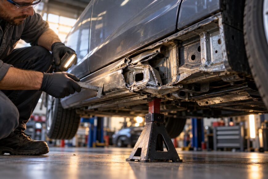
Raise a unibody car on a damaged sill, and the jack may push the jacking point farther inward even when the outside still looks acceptable. A crushed pinch weld, torn reinforcement, or folded sill may already have changed how the body carries lifting and crash loads.
The quick solution is usually to straighten the metal, weld over the damage, apply filler, and paint it. That may improve the appearance without restoring the body’s geometry or structural function. A sound repair depends on the vehicle’s control-point measurements, the material used in the damaged area, and the manufacturer’s approved procedure; there is no universal DIY fix for a compromised unibody jacking point.
- What a Damaged Sill Jacking Point Really Means
- Inspect the Structure Before Choosing a Repair
- When to Straighten, Replace, or Stop the Repair
- How a Structural Sill Repair Should Be Executed
- Why Quick Jacking-Point Fixes Fail Later
- Verify the Repair Before Returning the Car to Service
- Frequently Asked Questions
- Where are the best lift points on a unibody car?
- What is the 3/4 rule for floor jacks?
- What proof should a repair shop provide after fixing a unibody jacking point?
What a Damaged Sill Jacking Point Really Means
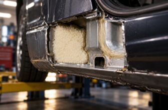
A sill is the structural side section beneath the doors. It may contain an outer panel, inner reinforcement, a pinch-weld flange, and local strengthening around the manufacturer’s approved lifting location. On a unibody car, these parts form part of the load-bearing body shell rather than acting as a simple, replaceable lifting tab.
The jacking point may connect load paths through the floor, pillars, rocker reinforcement, and nearby attachment areas. If the point collapses, the visible dent may be only the outer evidence of deeper deformation. Folds, torn metal, microcracks, and movement around adjacent mounting areas can remain hidden behind trim, coatings, or underbody protection.
Control points are manufacturer-defined body reference points used to assess shell geometry. A vehicle can look straight from the outside while those points have shifted outside the manufacturer’s tolerances. That kind of deviation calls for structural assessment and correction, not cosmetic finishing.
Construction differs between models, including the materials, reinforcements, joining methods, and permitted repair zones. A repair method that is acceptable for one sill may be unsafe for another, particularly where high-strength steel or integrated attachment structures are involved.
Inspect the Structure Before Choosing a Repair
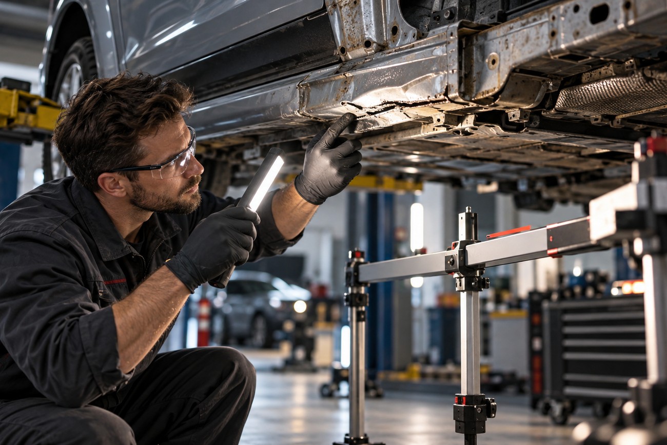
Begin by confirming the vehicle manufacturer’s approved lifting location. Remove obstructing trim or underbody protection where necessary, then inspect the sill, pinch weld, reinforcement, floor edge, and nearby attachments for folds, tears, gaps, buckling, and damaged coatings. Do not place a jack under a visibly weakened section merely to see whether it holds.
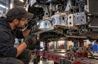
After a significant impact or an overload from incorrect jacking, visual inspection is insufficient on its own. The body should be secured and measured against the manufacturer’s control-point data. A frame machine with a measuring system can reveal a shifted reference point that is impossible to judge reliably from panel gaps or an apparently level sill.
Control-point deviations beyond the manufacturer’s tolerances indicate serious structural repair rather than cosmetic correction. The inspection should also consider door fit, latch operation, suspension attachment points, subframe or other mounting areas, and any nearby structure that could have absorbed the load.
Look for secondary signs such as a door that no longer closes cleanly, a latch that requires force, uneven gaps, new wind noise, or a steering wheel that is no longer centered after the incident. These signs do not prove a particular failure, but they justify a complete measurement and related-component check.
The written repair information for the exact vehicle should determine the next step. It identifies permissible measuring points, material restrictions, joining methods, and whether a damaged component may be corrected, sectioned, or replaced.
When to Straighten, Replace, or Stop the Repair
Limited straightening is permitted only when the manufacturer explicitly allows correction for that specific component, material, and degree of deformation. A small distortion in an approved repair zone may be treatable under that procedure. “It is only slightly bent” is not a technical approval.
Folded, torn, cracked, or heavily deformed metal should not automatically be left in place and covered. A surface weld, filler, or paint can hide the damage while leaving the original load path compromised. If the procedure calls for removal, the non-repairable section must be cut out and replaced as specified.
High-strength steel requires particular caution. Its repair, heating, straightening, and replacement limits depend on the material, the component, the damage severity, and the manufacturer’s instructions. Severe deformation may make repair prohibited or restrict it to a procedure that does not involve conventional reshaping.
Damage can extend beyond the visible jacking point into neighboring attachment areas. In that situation, the approved replacement may need to include more than the crushed flange or outer sill skin. The extent should be established by measurement and inspection rather than by the size of the visible mark.
If the repair information is unavailable, the material cannot be identified, or the shell cannot be returned to the required geometry, improvisation is an unsafe substitute. The appropriate decision may be to pause the work until the vehicle-specific procedure and parts are confirmed.
How a Structural Sill Repair Should Be Executed
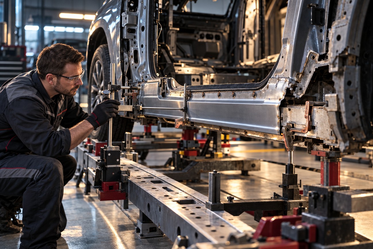
The shell should first be secured and restored to the correct position on a measuring system. This establishes whether the sill, floor, pillars, and related attachment points are aligned before damaged material is removed. The repair plan should then identify the non-repairable section, the approved replacement section, and the specified joints and sequence.
Non-repairable material may need to be cut out, with the replacement fitted accurately to the surrounding structure. The replacement must match the approved design and be positioned without forcing adjacent panels into place. Generic metal thicknesses, weld lengths, and welding settings cannot be applied safely across different vehicles.
Releasing tension or welding against an unmeasured, shifted shell can lock incorrect geometry into the repair. The body must be verified before cutting and again while the replacement section is positioned.
Structural joining should follow the manufacturer’s approved method and sequence. Depending on the vehicle, that may include spot welding, MIG welding, or brazing in a controlled protective atmosphere. The process must account for the original construction and the limits of the material, especially in heat-sensitive high-strength steel.
Finishing is part of the repair. Seam sealing, corrosion protection, and restoration of coatings in the heat-affected area protect the repaired load path from water and corrosion. Leaving bare metal, damaged coating, or an open seam can reduce durability even when the weld itself appears acceptable.
Why Quick Jacking-Point Fixes Fail Later
A shop can make a sill look straight without restoring its factory geometry. Straightening, filler, paint, or a surface weld does not by itself restore the original strength or the position of the manufacturer’s control points. The result may pass a visual check while the door, latch, or adjacent structure remains misaligned.
Skipped measurements are one reason a later door problem is blamed on the door rather than the repair. A shifted sill or pillar can change panel gaps and latch alignment, while hidden deformation may affect nearby mounting points. The same underlying error can contribute to a steering wheel that sits off-center or a vehicle that does not track as expected.
Heat control and joining sequence also matter. Retaining torn metal, applying heat without the approved procedure, or welding a replacement against an incorrectly positioned shell can leave a weakened or distorted structure. These faults may be concealed beneath sealant and paint until the vehicle is loaded again.
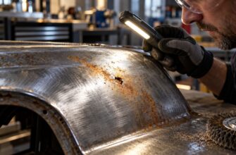
Rust is another delayed failure. Missing seam sealer or weak corrosion protection allows moisture into the weld and heat-affected area, where damage may develop beneath an apparently sound finish. Even a properly restored area can remain a compromise in fatigue life and corrosion resistance compared with an undamaged factory assembly.
Verify the Repair Before Returning the Car to Service

Every repair of a structural jacking area requires a post-repair geometry check. The body control points should be remeasured against the manufacturer’s data, with the results recorded rather than replaced by a statement that the panels “line up.” Panel alignment is useful, but it is not proof that the shell is within the required geometry.
The final inspection should cover the welds, joint preparation, seam sealing, and corrosion protection, including coatings in the heat-affected area. Doors and latches should open, close, and engage normally. Related suspension attachment points, subframe or other mounting areas, and nearby body fittings should be checked where the damage could have transferred load.
Ask the repair shop for the vehicle-specific repair procedure used, measurement results before and after correction, and details of the replacement section or parts. Photographs of the exposed damage and completed joints may be useful where appropriate. The records should also confirm that seam sealing and corrosion protection were restored.
A vehicle should not be released solely because its exterior looks aligned. The manufacturer’s repair documentation governs acceptable geometry, materials, and joining methods, and the final records provide a practical way to confirm that those requirements were considered.
Frequently Asked Questions
Safe lifting and repair decisions depend on the vehicle’s own instructions and the condition of its structure. General rules can help frame the decision, but they do not replace the owner’s manual, manufacturer repair data, or proper support equipment.
Where are the best lift points on a unibody car?
The best lift points are the locations identified in the owner’s manual and the manufacturer’s lifting diagrams. Depending on the model, these may include marked pinch-weld points, approved subframe locations, or intact reinforced lift pads.
A damaged, folded, or weakened sill section should be avoided even if it resembles the marked location. Use only an approved, intact point, and follow the vehicle and jack manufacturer’s instructions for supporting the car after lifting.
What is the 3/4 rule for floor jacks?
The commonly cited 3/4 rule of thumb says that a floor jack’s rated capacity should cover at least three-quarters of the vehicle’s weight. It is only a rough selection guide and does not confirm that the jack is suitable for a particular lifting operation.
The jack’s rating, the vehicle manufacturer’s lifting instructions, the ground conditions, and the use of correctly rated support stands take priority. Never treat the rule as permission to lift at a damaged jacking point or to work beneath a vehicle supported only by a jack.
What proof should a repair shop provide after fixing a unibody jacking point?
Request the vehicle-specific repair procedure, pre- and post-repair measurement results, and a description of the replacement section or structural parts used. Photographs showing the damage, prepared joints, and completed repair can provide useful supporting evidence where appropriate.
The documentation should also confirm inspection of related mounting, suspension, door, and latch areas when relevant, along with seam sealing and corrosion protection. If the shop cannot explain how the control points were verified, a cosmetic finish alone is insufficient evidence of a completed structural repair.